
Arduino Nano Controlled Servo System with Joystick and Pushbutton Interaction
View and Edit Project In Cirkit Designer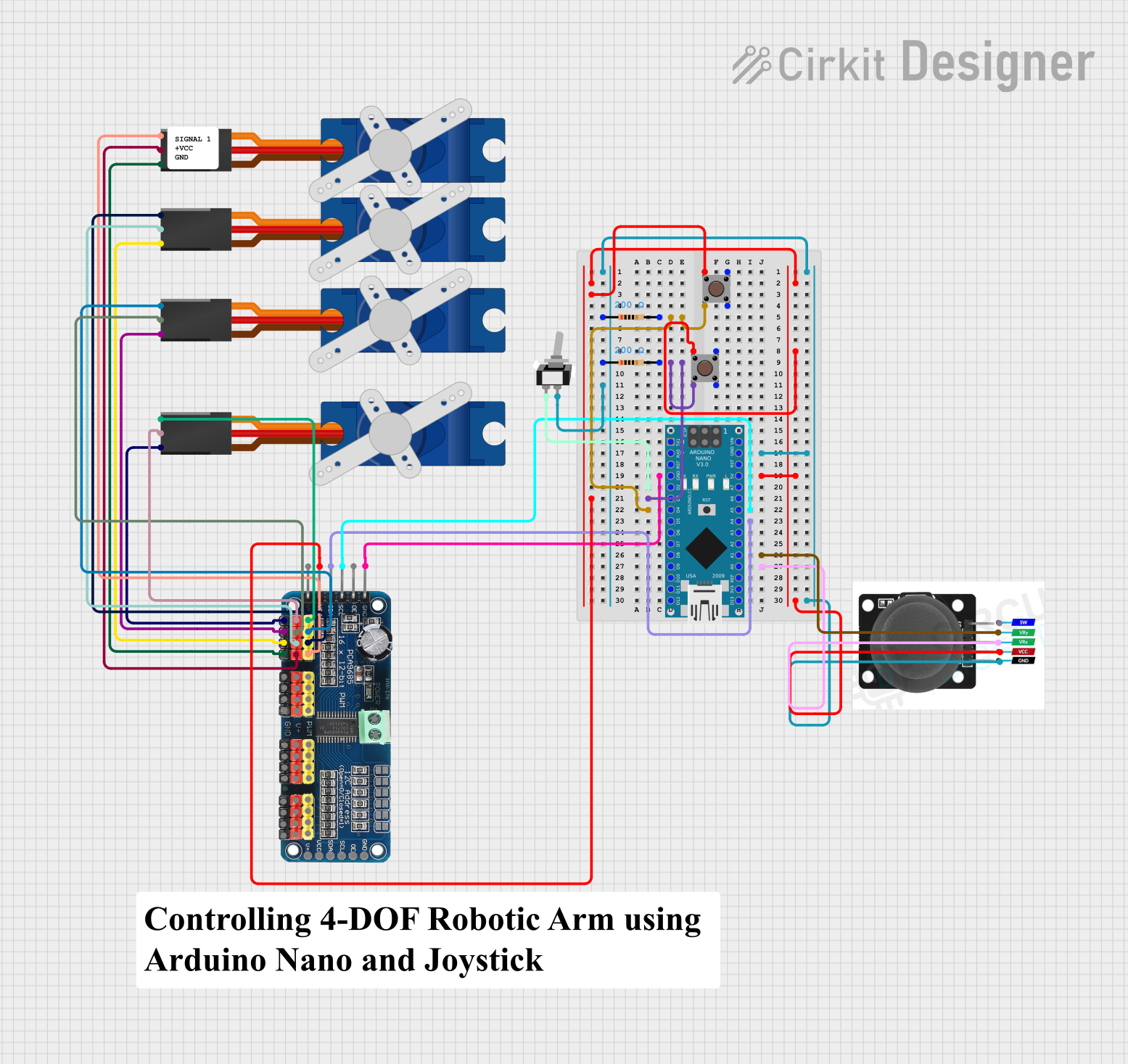
Circuit Documentation
Summary
The circuit in question is designed to interface an Arduino Nano with a 16-Channel PWM Servo Driver, multiple Tower Pro SG90 servos, a joystick module, and pushbuttons. The Arduino Nano serves as the central microcontroller, processing inputs from the joystick and pushbuttons to control the servos via the PWM driver. The servos are powered by the PWM driver, which is in turn controlled by the Arduino Nano through I2C communication. The pushbuttons are used to trigger specific actions or modes, and the joystick provides analog input for dynamic control.
Component List
Microcontroller
- Arduino Nano: A compact microcontroller board based on the ATmega328P, featuring digital and analog I/O pins.
Driver
- 16-Channel PWM Servo Driver: A board capable of driving up to 16 servos with Pulse Width Modulation (PWM).
Servos
- Tower Pro SG90 Servo: Small and lightweight servos for precise motion control.
Input Devices
- Pushbutton: A simple switch mechanism for control of a machine or some type of process.
- Joystick Module: An input device consisting of a stick that pivots on a base and reports its angle or direction to the device it is controlling.
Passive Components
- Resistor: A passive two-terminal electrical component that implements electrical resistance as a circuit element.
- Toggle Switch (SPST): A single pole single throw switch that can connect or disconnect the circuit.
Miscellaneous
- Comment: A non-electrical component used for leaving notes or comments in the circuit design.
Wiring Details
Arduino Nano
- Digital Pins
- D2 connected to Toggle Switch (SPST)
- D3 connected to Pushbutton (via 200 Ohm Resistor)
- D4 connected to Pushbutton (via 200 Ohm Resistor)
- Analog Pins
- A0 connected to Joystick Module (VRX)
- A1 connected to Joystick Module (VRY)
- A4 connected to 16-Channel PWM Servo Driver (SDA)
- A5 connected to 16-Channel PWM Servo Driver (SCL)
- Power Pins
- 5V connected to Pushbuttons, Joystick Module, and 16-Channel PWM Servo Driver (VCC)
- GND connected to Resistor, Joystick Module, Toggle Switch (SPST), and 16-Channel PWM Servo Driver (GND)
16-Channel PWM Servo Driver
- Control Pins
- SDA connected to Arduino Nano (A4)
- SCL connected to Arduino Nano (A5)
- Power Pins
- VCC connected to Arduino Nano (5V)
- GND connected to Arduino Nano (GND)
- V+ connected to Tower Pro SG90 Servos (+5V)
- PWM Output Pins
- PWM1 to PWM4 connected to Tower Pro SG90 Servos (Signal)
Tower Pro SG90 Servo
- Signal
- Connected to respective PWM output on 16-Channel PWM Servo Driver
- Power
- +5V connected to 16-Channel PWM Servo Driver (V+)
- GND connected to 16-Channel PWM Servo Driver (GND)
Pushbutton
- Pin 1 (in)
- Connected to Arduino Nano (5V)
- Pin 2 (in)
- Connected to Arduino Nano (D3 or D4) via 200 Ohm Resistor
Resistor
- Pin 1
- Connected to Arduino Nano (GND)
- Pin 2
- Connected to Pushbutton (Pin 2 in)
Toggle Switch (SPST)
- COM
- Connected to Arduino Nano (GND)
- L1
- Connected to Arduino Nano (D2)
Joystick Module
- VRX
- Connected to Arduino Nano (A0)
- VRY
- Connected to Arduino Nano (A1)
- VCC
- Connected to Arduino Nano (5V)
- GND
- Connected to Arduino Nano (GND)
Documented Code
Arduino Nano Code (sketch.ino)
void setup() {
  // put your setup code here, to run once:

}

void loop() {
  // put your main code here, to run repeatedly:

}
Note: The provided code is a template and does not contain any functional implementation. It needs to be filled with the logic for reading inputs from the joystick and pushbuttons, and controlling the servos via the PWM driver.