Cirkit Designer
Your all-in-one circuit design IDE
Home /
Project Documentation
Simple Pushbutton-Controlled LED Circuit
Circuit Documentation
Summary of the Circuit
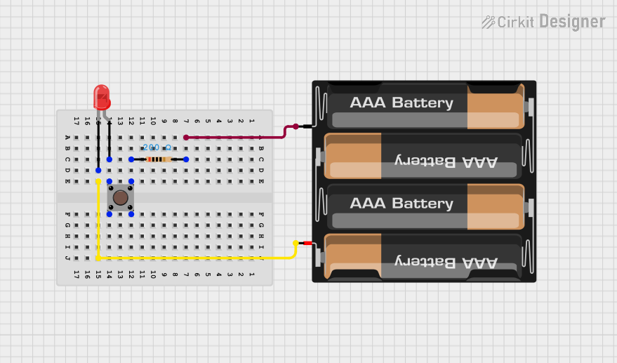
This circuit is a simple LED control circuit powered by a 4 x AAA battery mount. It includes a red two-pin LED, a pushbutton switch, and a resistor to limit the current through the LED. The LED lights up when the pushbutton is pressed. The circuit does not include any microcontrollers or embedded code.
Component List
LED: Two Pin (red)
- Description: A red light-emitting diode (LED) with two pins: an anode and a cathode.
- Purpose: To emit light when powered and current is flowing in the correct direction.
Pushbutton
- Description: A momentary pushbutton switch with four pins: two input pins and two output pins.
- Purpose: To allow the user to control the flow of current to the LED.
Resistor
- Description: A passive two-pin component with a specified resistance.
- Purpose: To limit the current flowing through the LED, protecting it from damage.
- Properties: 200 Ohms resistance.
4 x AAA Battery Mount
- Description: A battery holder for four AAA batteries with two pins: positive and negative.
- Purpose: To provide a power source for the circuit.
Wiring Details
LED: Two Pin (red)
- Cathode: Connected to the positive (+) terminal of the 4 x AAA Battery Mount.
- Anode: Connected to one of the input pins (Pin 1) of the Pushbutton.
Pushbutton
- Pin 1 (in): Connected to the anode of the LED.
- Pin 3 (out): Connected to one of the pins (pin1) of the Resistor.
Resistor
- Pin1: Connected to the output pin (Pin 3) of the Pushbutton.
- Pin2: Connected to the negative (-) terminal of the 4 x AAA Battery Mount.
4 x AAA Battery Mount
- Positive (+): Connected to the cathode of the LED.
- Negative (-): Connected to one of the pins (pin2) of the Resistor.
Documented Code
There is no embedded code provided for this circuit as it does not include any programmable components or microcontrollers.