Cirkit Designer
Your all-in-one circuit design IDE
Home /
Project Documentation
Arduino UNO Flame Detection System with LED Indicators and Buzzer Alert
Circuit Documentation
Summary
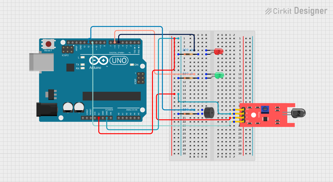
This circuit is designed to detect the presence of a flame using a KY-026 Flame Sensor. When a flame is detected, a red LED and a buzzer are activated. If no flame is detected, a green LED is turned on. The circuit is controlled by an Arduino UNO microcontroller.
Component List
LED: Two Pin (red)
- Description: A red LED used to indicate the presence of a flame.
- Pins: Cathode, Anode
KY-026 Flame Sensor
- Description: A sensor used to detect the presence of a flame.
- Pins: A0, GND, VCC, D0
Arduino UNO
- Description: A microcontroller used to control the circuit.
- Pins: UNUSED, IOREF, Reset, 3.3V, 5V, GND, Vin, A0, A1, A2, A3, A4, A5, SCL, SDA, AREF, D13, D12, D11, D10, D9, D8, D7, D6, D5, D4, D3, D2, D1, D0
LED: Two Pin (green)
- Description: A green LED used to indicate the absence of a flame.
- Pins: Cathode, Anode
Buzzer
- Description: A buzzer used to provide an audible alert when a flame is detected.
- Pins: PIN, GND
Resistor (200 Ohms)
- Description: A resistor used to limit the current through the LEDs and buzzer.
- Pins: Pin1, Pin2
Wiring Details
LED: Two Pin (red)
- Cathode: Connected to D5 on the Arduino UNO.
- Anode: Connected to Pin2 of a 200 Ohm resistor.
- Resistor Pin1: Connected to GND on the Arduino UNO.
KY-026 Flame Sensor
- VCC: Connected to 5V on the Arduino UNO.
- GND: Connected to GND on the Arduino UNO.
- D0: Connected to D11 on the Arduino UNO.
Arduino UNO
- 5V: Connected to VCC of the KY-026 Flame Sensor.
- GND: Connected to GND of the KY-026 Flame Sensor and Pin1 of the 200 Ohm resistors.
- D5: Connected to the Cathode of the red LED.
- D6: Connected to the Cathode of the green LED.
- D11: Connected to D0 of the KY-026 Flame Sensor.
- D12: Connected to the PIN of the buzzer.
LED: Two Pin (green)
- Cathode: Connected to D6 on the Arduino UNO.
- Anode: Connected to Pin2 of a 200 Ohm resistor.
- Resistor Pin1: Connected to GND on the Arduino UNO.
Buzzer
- PIN: Connected to D12 on the Arduino UNO.
- GND: Connected to Pin2 of a 200 Ohm resistor.
- Resistor Pin1: Connected to GND on the Arduino UNO.
Code Documentation
const int buzzerPin = 12;
const int flamePin = 11;
int Flame = HIGH;
int redled = 5;
int greenled = 6;

void setup()
{
  pinMode(buzzerPin, OUTPUT);
  pinMode(redled, OUTPUT);
  pinMode(greenled, OUTPUT);
  pinMode(flamePin, INPUT);
  Serial.begin(9600);
}

void loop()
{
  Flame = digitalRead(flamePin);
  if (Flame == LOW)
  {
    digitalWrite(buzzerPin, HIGH);
    digitalWrite(redled, HIGH);
    digitalWrite(greenled, LOW);
  }
  else
  {
    digitalWrite(buzzerPin, LOW);
    digitalWrite(greenled, HIGH);
    digitalWrite(redled, LOW);
  }
}
Code Explanation
Pin Definitions:
buzzerPinis connected to pin 12 on the Arduino.flamePinis connected to pin 11 on the Arduino.redledis connected to pin 5 on the Arduino.greenledis connected to pin 6 on the Arduino.
Setup Function:
- Sets the
buzzerPin,redled, andgreenledas OUTPUT. - Sets the
flamePinas INPUT. - Initializes serial communication at 9600 baud rate.
- Sets the
Loop Function:
- Reads the state of the
flamePin. - If a flame is detected (
Flame == LOW), the buzzer and red LED are turned on, and the green LED is turned off. - If no flame is detected, the buzzer and red LED are turned off, and the green LED is turned on.
- Reads the state of the