Arduino Uno Based Gas Detection System with MQ-5 Sensor and Alert Indicators
Gas Detection System Circuit Documentation
Summary
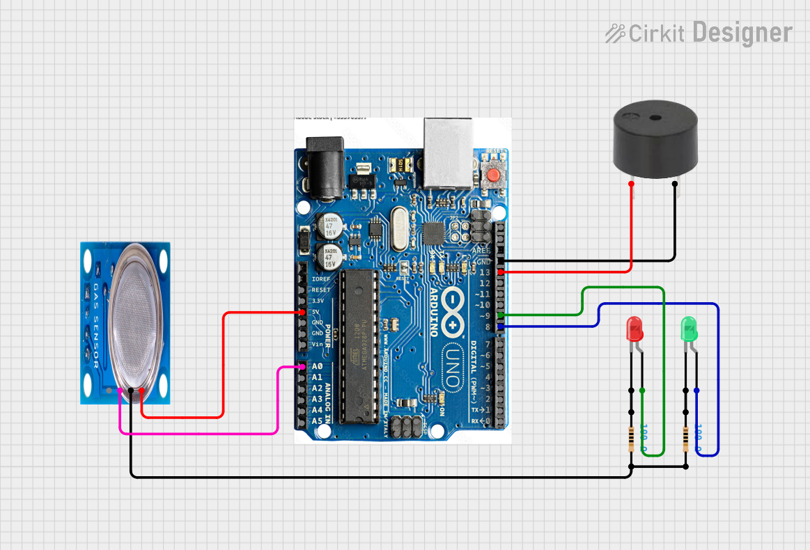
This circuit is designed to create a gas detection system using an Arduino Uno microcontroller and an MQ-5 gas sensor. When the sensor detects gas, the system activates a buzzer and a red LED as a warning signal. Conversely, when no gas is detected, a green LED indicates that the environment is safe. The circuit includes resistors to limit current to the LEDs, ensuring they operate within safe parameters.
Component List
Arduino Uno
- Microcontroller board based on the ATmega328P
- It has 14 digital input/output pins, 6 analog inputs, a 16 MHz quartz crystal, a USB connection, a power jack, an ICSP header, and a reset button.
MQ-5 Gas Sensor
- A gas sensor designed for detecting LPG, natural gas, and coal gas
- It has a digital output and an analog output.
Buzzer
- An electromechanical component that produces sound
- Used to alert users when gas is detected.
LED: Two Pin (Red)
- A red light-emitting diode used as an indicator
- Lights up when gas is detected.
LED: Two Pin (Green)
- A green light-emitting diode used as an indicator
- Lights up when no gas is detected.
Resistor (100 Ohms)
- Two resistors with a resistance of 100 Ohms each
- Used to limit the current through the LEDs.
Wiring Details
Arduino Uno
- GROUND connected to the buzzer's GND and the common ground of the circuit.
- Pin 13 (SCK) connected to the buzzer's PIN.
- Pin 9 connected to the anode of the red LED.
- Pin 8 connected to the anode of the green LED.
- Pin A0 connected to the MQ-5 gas sensor's digital output.
- 5V connected to the MQ-5 gas sensor's VCC.
MQ-5 Gas Sensor
- VCC connected to the Arduino's 5V.
- GND connected to the common ground through a 100 Ohm resistor.
- Digi Out connected to the Arduino's A0.
Buzzer
- PIN connected to the Arduino's pin 13 (SCK).
- GND connected to the Arduino's GROUND.
LED: Two Pin (Red)
- Anode connected to the Arduino's pin 9.
- Cathode connected to a 100 Ohm resistor leading to the common ground.
LED: Two Pin (Green)
- Anode connected to the Arduino's pin 8.
- Cathode connected to a 100 Ohm resistor leading to the common ground.
Resistor (100 Ohms)
- One resistor connected between the red LED's cathode and the common ground.
- Another resistor connected between the green LED's cathode and the common ground.
Documented Code
/*
 * This Arduino Sketch controls a gas detection system using an MQ-5 sensor.
 * When gas is detected, a buzzer and a red LED are activated.
 * When no gas is detected, a green LED is activated.
 */

const int buzzerPin = 13; // Buzzer connected to pin 13 (SCK)
const int greenLEDPin = 8; // Green LED connected to pin 8
const int redLEDPin = 9; // Red LED connected to pin 9
const int gasSensorPin = A0; // MQ-5 gas sensor digital output connected to A0

void setup() {
  pinMode(buzzerPin, OUTPUT); // Set buzzer pin as output
  pinMode(greenLEDPin, OUTPUT); // Set green LED pin as output
  pinMode(redLEDPin, OUTPUT); // Set red LED pin as output
  pinMode(gasSensorPin, INPUT); // Set gas sensor pin as input
}

void loop() {
  int gasDetected = digitalRead(gasSensorPin); // Read gas sensor value
  if (gasDetected == HIGH) { // If gas is detected
    digitalWrite(buzzerPin, HIGH); // Turn on buzzer
    digitalWrite(redLEDPin, HIGH); // Turn on red LED
    digitalWrite(greenLEDPin, LOW); // Turn off green LED
  } else { // If no gas is detected
    digitalWrite(buzzerPin, LOW); // Turn off buzzer
    digitalWrite(redLEDPin, LOW); // Turn off red LED
    digitalWrite(greenLEDPin, HIGH); // Turn on green LED
  }
}
This code is designed to be uploaded to the Arduino Uno microcontroller. It initializes the pins connected to the buzzer and LEDs as outputs and the gas sensor pin as an input. In the main loop, it continuously checks the gas sensor's digital output. If gas is detected, it activates the buzzer and red LED while deactivating the green LED. If no gas is detected, it deactivates the buzzer and red LED while activating the green LED.