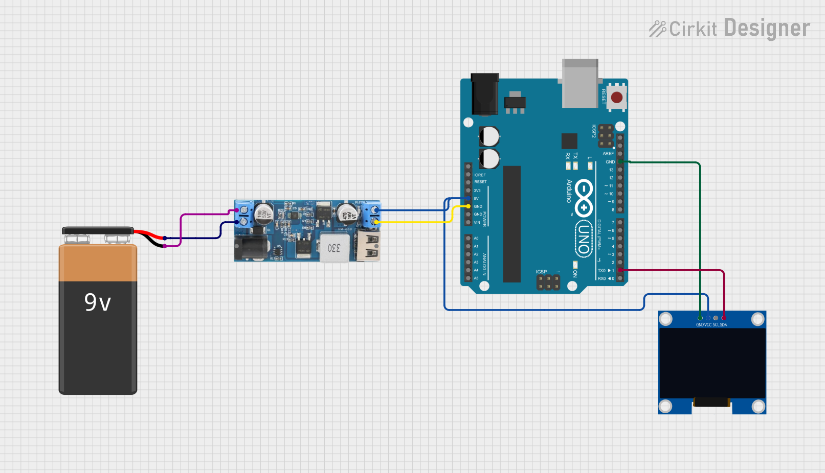
Arduino UNO Controlled OLED Display with 9V Battery and Step-Down Converter

Circuit Documentation
Summary
This circuit consists of an Arduino UNO microcontroller, a 9V battery, a 128x64 OLED display with I2C communication, and a 12V to 5V step-down power converter. The Arduino UNO is used as the central processing unit, controlling the OLED display and managing the input/output operations. The 9V battery provides power to the circuit, which is regulated to 5V by the step-down converter to power the Arduino and the OLED display. The OLED display is interfaced with the Arduino via I2C communication protocol for displaying data.
Component List
Arduino UNO
- Microcontroller board based on the ATmega328P
- It has 14 digital input/output pins, 6 analog inputs, a 16 MHz quartz crystal, a USB connection, a power jack, an ICSP header, and a reset button.
9V Battery
- Standard 9V battery used as the power source for the circuit.
128x64 OLED Display (I2C IIC SPI Serial)
- A small display screen that uses OLED technology for high contrast and visibility.
- It supports I2C communication, which requires only two data connections.
12v to 5v Step Down Power Converter
- A power converter that steps down the input voltage from 9V-36V to a stable 5V output.
- It has a USB output and a 5V output pin for powering devices.
Wiring Details
Arduino UNO
- 5V: Connected to the 5V output of the step-down power converter and VCC of the OLED display.
- GND: Common ground with the step-down power converter and the OLED display.
- D1 (TX): Connected to the SDA pin of the OLED display for I2C data transmission.
9V Battery
- + (Positive): Connected to the VIN+ of the step-down power converter.
- - (Negative): Connected to the VIN- of the step-down power converter.
128x64 OLED Display (I2C IIC SPI Serial)
- VCC: Powered by the 5V output from the Arduino UNO.
- GND: Common ground with the Arduino UNO.
- SDA: Connected to the D1 (TX) pin of the Arduino UNO for I2C data transmission.
- SCL: Not connected in this configuration.
12v to 5v Step Down Power Converter
- VIN 9v-36v: Not used in this configuration.
- VIN+: Connected to the positive terminal of the 9V battery.
- VIN-: Connected to the negative terminal of the 9V battery.
- USB OUTPUT 5V: Not used in this configuration.
- 5v OUTPUT: Provides power to the Arduino UNO and the OLED display.
- GND: Common ground with the Arduino UNO.
Documented Code
Arduino UNO Code: sketch.ino
void setup()
{
  // Initialize digital pin 13 as an output.
  pinMode(13, OUTPUT);
}

void loop()
{
  // Turn the LED on (HIGH is the voltage level)
  delay(1000);               // Wait for a second
  digitalWrite(13, HIGH);    // Turn the LED on by making the voltage HIGH

  // Turn the LED off by making the voltage LOW
  delay(1000);               // Wait for a second
  digitalWrite(13, LOW);     // Turn the LED off by making the voltage LOW
}
This code is designed to run on the Arduino UNO microcontroller. It sets up digital pin 13 as an output and then continuously toggles this pin between HIGH and LOW states, creating a blinking LED effect with a period of 2 seconds.