
Circuit Documentation
Summary
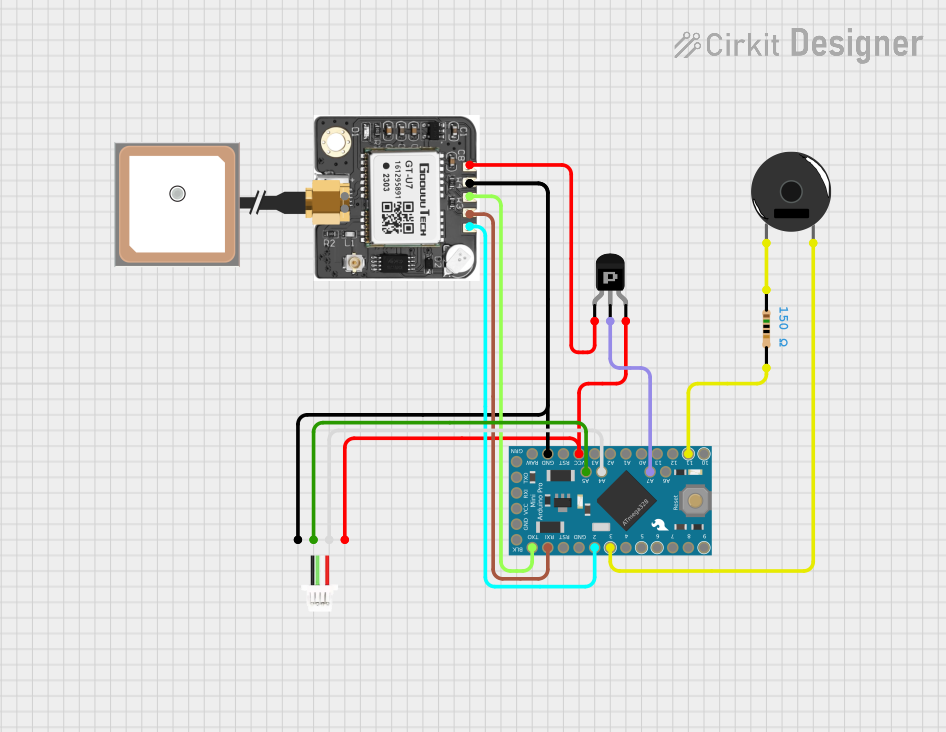
This document provides a detailed overview of a circuit that includes a Piezo Buzzer, a PNP Transistor, a GPS module, an embedded GPS antenna, a resistor, an Arduino Pro Mini, and a JST SH1 I2C connector. The circuit is designed to interface with a GPS module and provide audible feedback through a Piezo Buzzer. The Arduino Pro Mini serves as the main microcontroller, controlling the various components and handling data communication.
Component List
Piezo Buzzer
- Description: A device that produces sound when an electrical signal is applied.
- Pins: pin 1, pin 2
PNP Transistor (EBC)
- Description: A transistor used for switching and amplification.
- Pins: emitter, base, collector
neo 6m GPS
- Description: A GPS module used for receiving satellite signals and providing location data.
- Pins: VCC, GND, RXD, TXD, PPS
Antenna GPS Embedded SMA
- Description: An embedded GPS antenna with an SMA connector.
- Pins: VCC, GND
Resistor
- Description: A 150 Ohm resistor used to limit current.
- Pins: pin1, pin2
- Properties: Resistance: 150 Ohms
Arduino Pro Mini
- Description: A compact microcontroller board based on the ATmega328.
- Pins: DTR, TXO, RXI, VCC, GND, A4, A5, RAW, RESET, A3, A2, A1, A0, SCK, MISO, MOSI, D10, D9, D8, D7, D6, D5, D4, D3, D2, A7, A6
JST SH1 I2C
- Description: A connector for I2C communication.
- Pins: VCC, SCL, SDA, GND
Wiring Details
Piezo Buzzer
- pin 1 is connected to pin1 of the Resistor.
- pin 2 is connected to D3 of the Arduino Pro Mini.
PNP Transistor (EBC)
- collector is connected to VCC of the Arduino Pro Mini and VCC of the JST SH1 I2C.
- emitter is connected to VCC of the neo 6m GPS.
- base is connected to A7 of the Arduino Pro Mini.
neo 6m GPS
- GND is connected to GND of the Arduino Pro Mini and GND of the JST SH1 I2C.
- VCC is connected to emitter of the PNP Transistor.
- RXD is connected to TXO of the Arduino Pro Mini.
- TXD is connected to RXI of the Arduino Pro Mini.
- PPS is connected to D2 of the Arduino Pro Mini.
Antenna GPS Embedded SMA
- VCC and GND are not explicitly connected in the provided net list.
Resistor
- pin1 is connected to pin 1 of the Piezo Buzzer.
- pin2 is connected to MOSI of the Arduino Pro Mini.
Arduino Pro Mini
- D3 is connected to pin 2 of the Piezo Buzzer.
- VCC is connected to collector of the PNP Transistor and VCC of the JST SH1 I2C.
- A4 is connected to SCL of the JST SH1 I2C.
- A5 is connected to SDA of the JST SH1 I2C.
- GND is connected to GND of the neo 6m GPS and GND of the JST SH1 I2C.
- MOSI is connected to pin2 of the Resistor.
- A7 is connected to base of the PNP Transistor.
- TXO is connected to RXD of the neo 6m GPS.
- RXI is connected to TXD of the neo 6m GPS.
- D2 is connected to PPS of the neo 6m GPS.
JST SH1 I2C
- VCC is connected to collector of the PNP Transistor and VCC of the Arduino Pro Mini.
- SCL is connected to A4 of the Arduino Pro Mini.
- SDA is connected to A5 of the Arduino Pro Mini.
- GND is connected to GND of the neo 6m GPS and GND of the Arduino Pro Mini.
Documented Code
Arduino Pro Mini Code
void setup() {
  // put your setup code here, to run once:

}

void loop() {
  // put your main code here, to run repeatedly:

}
This code is a basic template for the Arduino Pro Mini. The setup function is where you initialize your components and settings, and the loop function is where the main logic of your program runs repeatedly.
Additional Documentation
This section is reserved for any additional documentation or notes that may be required for the circuit.