
Arduino UNO-Based Rain Detection and Alert System with Servo Control
View and Edit Project In Cirkit Designer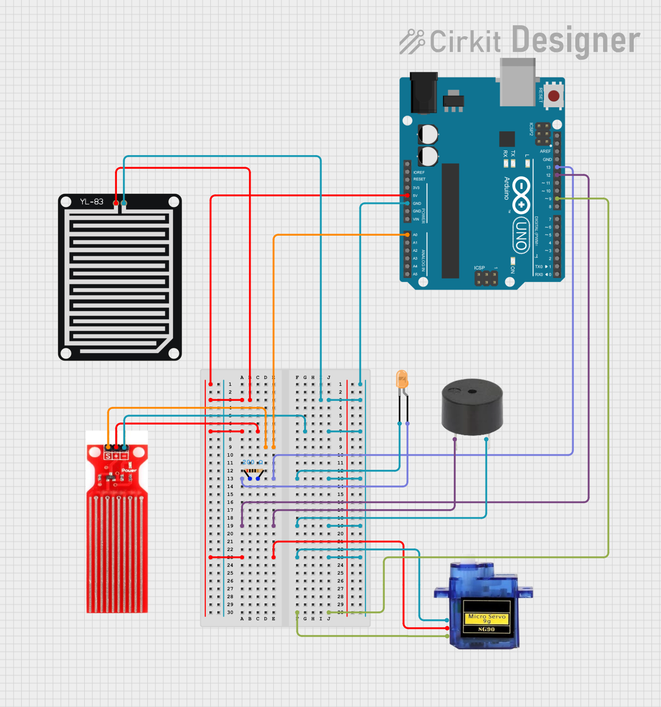
Circuit Documentation
Summary
This circuit integrates various components with an Arduino UNO microcontroller to perform a set of functions. The circuit includes a rain sensor, a water sensor, a micro servo, a buzzer, a resistor, and an LED. The Arduino UNO serves as the central processing unit, interfacing with the sensors to detect environmental conditions, controlling the servo, and providing visual and auditory feedback through the LED and buzzer.
Component List
Arduino UNO
- Description: A microcontroller board based on the ATmega328P.
- Pins: UNUSED, IOREF, Reset, 3.3V, 5V, GND, Vin, A0-A5, SCL, SDA, AREF, D13-D0
YL-83 Rain Sensor - Detection Board
- Description: A sensor used to detect raindrops.
- Pins: POS, NEG
Micro servo 9G
- Description: A small and lightweight servo motor for precise control.
- Pins: GND, +5V, PWM
Water sensor
- Description: A sensor used to detect the presence of water.
- Pins: Signal, VCC, GND
Buzzer
- Description: An electronic buzzer for audible alerts.
- Pins: PIN, GND
Resistor (200 Ohms)
- Description: A passive two-terminal electrical component that implements electrical resistance as a circuit element.
- Pins: pin1, pin2
- Resistance: 200 Ohms
LED: Two Pin (orange)
- Description: A small light-emitting diode for visual indication.
- Pins: cathode, anode
Wiring Details
Arduino UNO
- 5V: Connected to POS of YL-83 Rain Sensor, VCC of Water sensor, and +5V of Micro servo 9G.
- GND: Common ground with YL-83 Rain Sensor (NEG), Water sensor (GND), LED (cathode), Buzzer (GND), and Micro servo 9G (GND).
- A0: Connected to Signal of Water sensor.
- D13: Connected through a 200 Ohm resistor to the anode of the LED.
- D12: Connected to PIN of Buzzer.
- D9: Connected to PWM of Micro servo 9G.
YL-83 Rain Sensor - Detection Board
- POS: Connected to 5V of Arduino UNO.
- NEG: Connected to common ground.
Micro servo 9G
- GND: Connected to common ground.
- +5V: Connected to 5V of Arduino UNO.
- PWM: Controlled by D9 of Arduino UNO.
Water sensor
- Signal: Connected to A0 of Arduino UNO.
- VCC: Connected to 5V of Arduino UNO.
- GND: Connected to common ground.
Buzzer
- PIN: Controlled by D12 of Arduino UNO.
- GND: Connected to common ground.
Resistor (200 Ohms)
- pin1: Connected to D13 of Arduino UNO.
- pin2: Connected to the anode of the LED.
LED: Two Pin (orange)
- cathode: Connected to common ground.
- anode: Connected through a 200 Ohm resistor to D13 of Arduino UNO.
Documented Code
Arduino UNO Code (sketch.ino)
void setup() {
  // put your setup code here, to run once:

}

void loop() {
  // put your main code here, to run repeatedly:

}
Additional Notes
- The provided code is a template and does not include specific functionality. It needs to be populated with the logic to read sensors, control the servo, and activate the buzzer and LED based on sensor inputs.
- The
setup()function is intended for initialization code that runs once, such as setting pin modes. - The
loop()function is for code that runs continuously, which will include the main logic of the circuit's operation.