
Arduino Nano Based GPS Tracker with LoRa Communication and LED Indicator
View and Edit Project In Cirkit Designer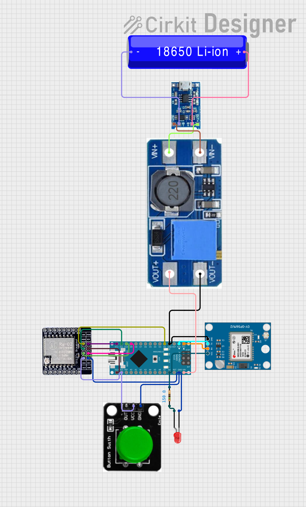
Circuit Documentation
Summary
This circuit integrates various components to interface with an Arduino Nano microcontroller. The design includes a Neo 6M GPS Module for location tracking, a LORA_RA02 module for long-range communication, and a simple LED indicator with a resistor. Power management is handled by a 18650 Li-ion Battery connected to a lipo battery charger module, which in turn connects to a Step Up Boost Power Converter to regulate the voltage supplied to the Arduino Nano. A green button is included for user input. The circuit's functionality is controlled by embedded code running on the Arduino Nano.
Component List
Arduino Nano
A compact microcontroller board based on the ATmega328P, featuring digital and analog I/O pins, communication interfaces, and onboard voltage regulators.
18650 Li-ion Battery
A rechargeable battery providing a power source for the circuit.
Lipo Battery Charger Module
A module designed to charge the 18650 Li-ion Battery safely.
LED: Two Pin (red)
A red light-emitting diode used as an indicator light in the circuit.
Green Button
A pushbutton switch that allows user interaction with the circuit.
LORA_RA02
A long-range communication module based on LoRa technology, enabling wireless data transmission over long distances.
Neo 6M GPS Module
A GPS receiver module that provides location data to the microcontroller.
Step Up Boost Power Converter, Adjustable Voltage Regulator
A voltage regulator that steps up the input voltage to a higher, adjustable output voltage.
Resistor (150 Ohms)
A passive electrical component that provides resistance in the circuit, used here to limit current to the LED.
Wiring Details
Arduino Nano
D1/TXconnected toRXon Neo 6M GPS ModuleD0/RXconnected toTXon Neo 6M GPS ModuleGNDconnected to common ground netD2connected toIO_0on LORA_RA02D9connected toRSTon LORA_RA02D10connected toNSSon LORA_RA02D11/MOSIconnected toMOSIon LORA_RA02D12/MISOconnected toMISOon LORA_RA02VINconnected toVOUT+on Step Up Boost Power Converter5Vconnected to one end of the Resistor andVCCon Neo 6M GPS Module3V3connected to3V3on LORA_RA02 andVCCon Green ButtonD13/SCKconnected toSCKon LORA_RA02
18650 Li-ion Battery
-connected toB-on lipo battery charger module+connected toB+on lipo battery charger module
Lipo Battery Charger Module
OUT-connected toVIN-on Step Up Boost Power ConverterOUT+connected toVIN+on Step Up Boost Power Converter
LED: Two Pin (red)
cathodeconnected to common ground netanodeconnected to the other end of the Resistor
Green Button
OUT(not connected in the provided net list)VCCconnected to3V3on Arduino NanoGNDconnected to common ground net
LORA_RA02
GNDconnected to common ground net- Other pins connected as per Arduino Nano wiring details
Neo 6M GPS Module
GNDconnected to common ground netTXconnected toD0/RXon Arduino NanoRXconnected toD1/TXon Arduino NanoVCCconnected to one end of the Resistor
Step Up Boost Power Converter, Adjustable Voltage Regulator
VOUT+connected toVINon Arduino NanoVOUT-connected to common ground netVIN+connected toOUT+on lipo battery charger moduleVIN-connected toOUT-on lipo battery charger module
Resistor (150 Ohms)
pin1connected toanodeon LED: Two Pin (red)pin2connected to5Von Arduino Nano andVCCon Neo 6M GPS Module
Documented Code
Arduino Nano - sketch.ino
void setup() {
  // put your setup code here, to run once:

}

void loop() {
  // put your main code here, to run repeatedly:

}
Arduino Nano - documentation.txt
(No additional documentation provided for the code)
This concludes the documentation for the provided circuit design. The circuit is designed for communication and location tracking purposes, with power management and user interaction capabilities. The embedded code for the Arduino Nano is minimal and serves as a template for further development.