Cirkit Designer
Your all-in-one circuit design IDE
Home /
Project Documentation
Arduino UNO Controlled 8x8 LED Matrix Display with Touch Sensor
Circuit Documentation
Summary
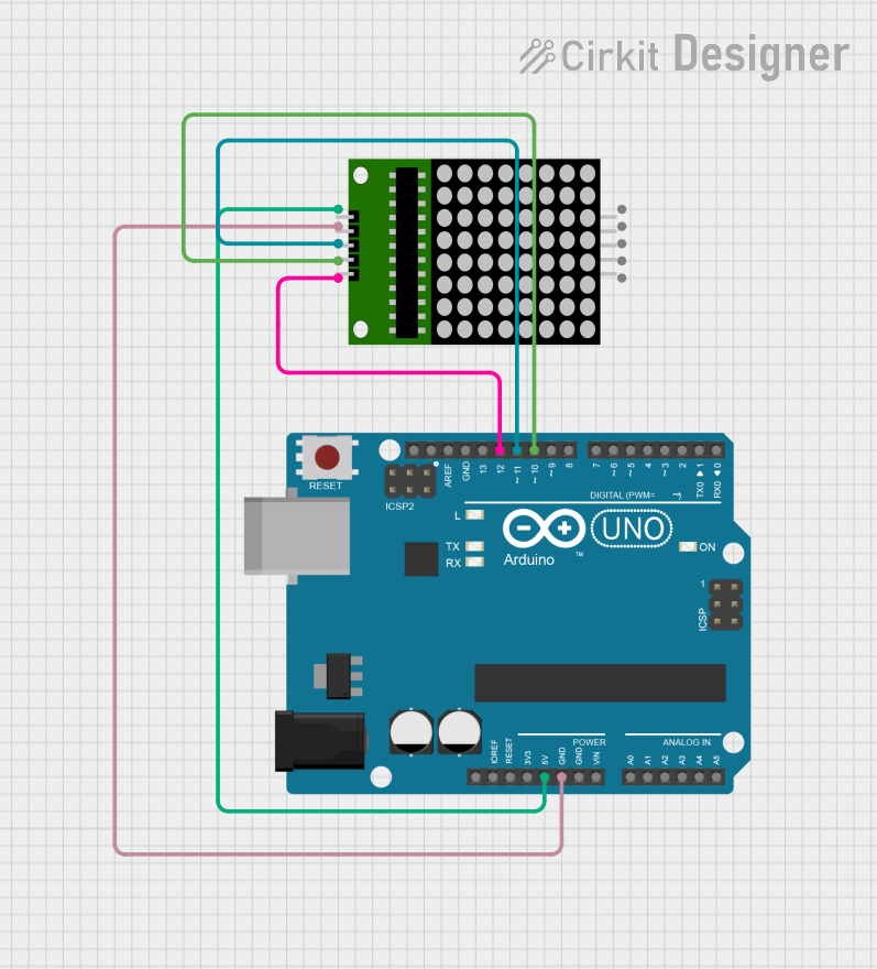
This circuit consists of an Arduino UNO microcontroller connected to an 8x8 LED matrix. The Arduino UNO provides power and control signals to the LED matrix, allowing it to display patterns or messages. The microcontroller is programmed to read an input pin and control an LED based on the input state.
Component List
Arduino UNO
- Description: A microcontroller board based on the ATmega328P.
- Pins: UNUSED, IOREF, Reset, 3.3V, 5V, GND, Vin, A0, A1, A2, A3, A4, A5, SCL, SDA, AREF, D13, D12, D11, D10, D9, D8, D7, D6, D5, D4, D3, D2, D1, D0
8x8 Matrix
- Description: An 8x8 LED matrix display.
- Pins: vcc, DIN, clk, CS, Gnd, gnd, CLK
Wiring Details
Arduino UNO
- 5V: Connected to vcc of the 8x8 matrix.
- GND: Connected to Gnd of the 8x8 matrix.
- D12: Connected to CS of the 8x8 matrix.
- D11: Connected to DIN of the 8x8 matrix.
- D10: Connected to clk of the 8x8 matrix.
8x8 Matrix
- vcc: Connected to 5V of the Arduino UNO.
- Gnd: Connected to GND of the Arduino UNO.
- CS: Connected to D12 of the Arduino UNO.
- DIN: Connected to D11 of the Arduino UNO.
- clk: Connected to D10 of the Arduino UNO.
Code Documentation
Arduino UNO Code
#define ctsPin 2

int ledPin = 13;

void setup()
{
    Serial.begin(9600);
    pinMode(ledPin, OUTPUT);
    pinMode(ctsPin, INPUT);
}

void loop()
{
    int ctsValue = digitalRead(ctsPin);
    if (ctsValue == HIGH)
    {
        digitalWrite(ledPin, HIGH);
        Serial.println("TOUCHED");
    }
    else
    {
        digitalWrite(ledPin, LOW);
        Serial.println("not touched");
    }
    delay(0.9);
}
Code Explanation
- ctsPin: Defines the pin number for the touch sensor input.
- ledPin: Defines the pin number for the onboard LED.
- setup(): Initializes serial communication, sets the LED pin as an output, and the touch sensor pin as an input.
- loop(): Continuously reads the state of the touch sensor. If the sensor is touched (HIGH), the LED is turned on and "TOUCHED" is printed to the serial monitor. If the sensor is not touched (LOW), the LED is turned off and "not touched" is printed to the serial monitor. The loop runs with a delay of 0.9 milliseconds.
This documentation provides a comprehensive overview of the circuit, including the components used, their connections, and the code running on the microcontroller.