
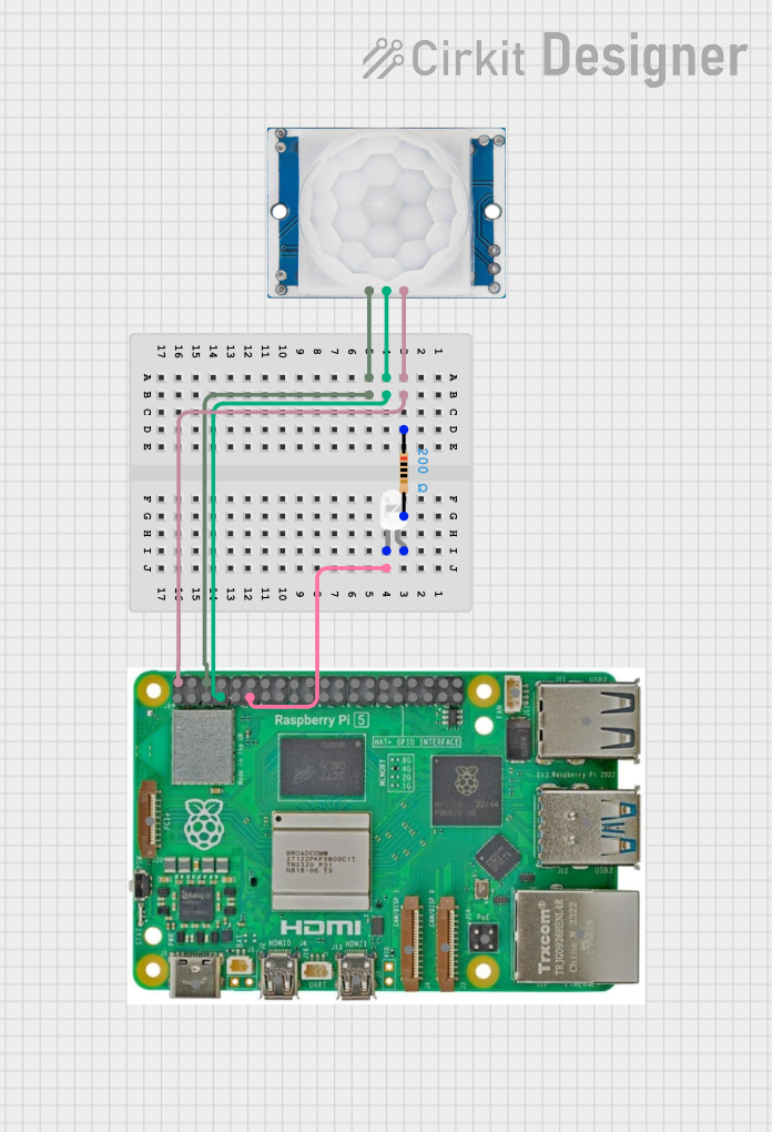
Circuit Documentation
Summary
This circuit integrates a PIR motion sensor, a Raspberry Pi 5, an LED, and a resistor. The PIR motion sensor detects motion and sends a signal to the Raspberry Pi, which then controls the LED. The resistor is used to limit the current flowing through the LED.
Component List
HC-SR501 PIR Motion Sensor
- Description: A motion sensor that detects infrared radiation.
- Pins: Output, Ground, Power Supply
- Purpose in Circuit: Detects motion and sends a signal to the Raspberry Pi.
Raspberry Pi 5
- Description: A single-board computer.
- Pins: Type-C, Micro HDMI 1, Micro HDMI 2, Camera 1, Camera 2, PoE, Fan, PCIe, USB 3.0, USB 2.0, Ethernet, 5V, GND, 3.3v, GPIO 14, GPIO 15, GPIO 18, GPIO 23, GPIO 24, GPIO 25, GPIO 8, GPIO 7, GPIO 1, GPIO 12, GPIO 16, GPIO 20, GPIO 21, GPIO 2, GPIO 3, GPIO 4, GPIO 17, GPIO 27, GPIO 22, GPIO 10, GPIO 9, GPIO 11, GPIO 0, GPIO 5, GPIO 6, GPIO 13, GPIO 19, GPIO 26
- Purpose in Circuit: Processes the signal from the PIR sensor and controls the LED.
LED: Two Pin (white)
- Description: A white LED.
- Pins: Cathode, Anode
- Purpose in Circuit: Provides visual indication when motion is detected.
Resistor
- Description: A resistor with a resistance of 200 Ohms.
- Pins: Pin1, Pin2
- Purpose in Circuit: Limits the current flowing through the LED.
Wiring Details
HC-SR501 PIR Motion Sensor
- Power Supply is connected to 5V on the Raspberry Pi.
- Output is connected to GPIO 4 on the Raspberry Pi.
- Ground is connected to GND on the Raspberry Pi.
Raspberry Pi 5
- 5V is connected to Power Supply on the PIR motion sensor.
- GPIO 4 is connected to Output on the PIR motion sensor.
- GND is connected to Ground on the PIR motion sensor.
- GPIO 17 is connected to Cathode on the LED.
LED: Two Pin (white)
- Cathode is connected to GPIO 17 on the Raspberry Pi.
- Anode is connected to Pin2 on the resistor.
Resistor
- Pin1 is connected to Power Supply on the PIR motion sensor.
- Pin2 is connected to Anode on the LED.
Code
There is no code provided for this circuit.