Cirkit Designer
Your all-in-one circuit design IDE
Home /
Project Documentation
Arduino UNO Controlled Dual PC Fan System with MOSFET Driver
Circuit Documentation
Summary
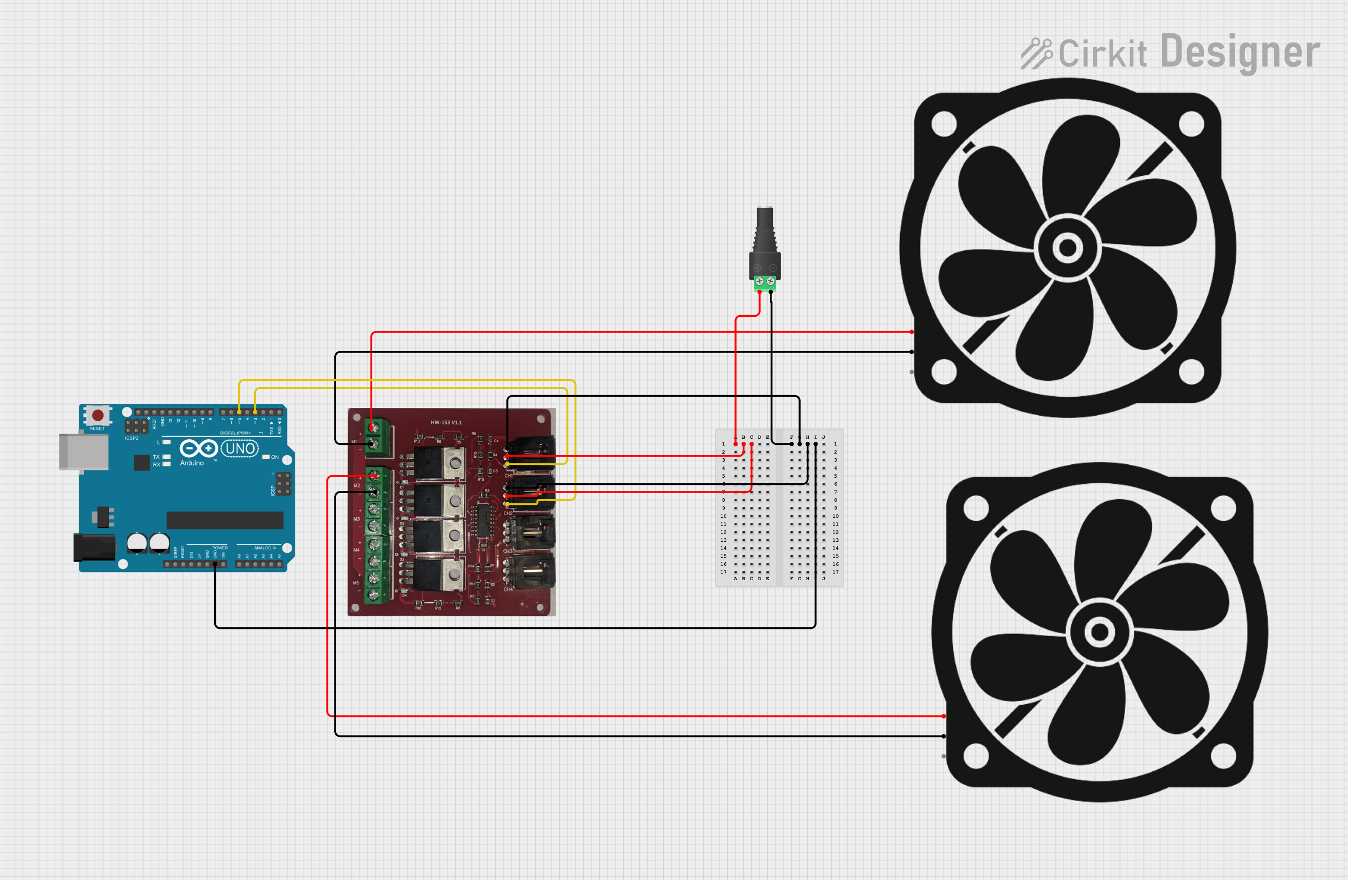
This circuit involves an Arduino UNO microcontroller, two PC fans, a 4 Channel MOSFET Driver, and a 2.1mm Barrel Jack with Terminal Block. The Arduino UNO controls the fans through the MOSFET driver, which allows for PWM control of the fans. The power is supplied through the barrel jack.
Component List
Arduino UNO
- Description: A microcontroller board based on the ATmega328P.
- Pins: UNUSED, IOREF, Reset, 3.3V, 5V, GND, Vin, A0, A1, A2, A3, A4, A5, SCL, SDA, AREF, D13, D12, D11, D10, D9, D8, D7, D6, D5, D4, D3, D2, D1, D0
PC Fan (Fan 1)
- Description: A standard PC fan.
- Pins: 12V, GND, PWM
PC Fan (Fan 2)
- Description: A standard PC fan.
- Pins: 12V, GND, PWM
4 Channel MOSFET Driver
- Description: A driver module for controlling high-power devices using MOSFETs.
- Pins: M5-, M5+, M4-, M4+, M3-, M3+, M2-, M2+, M1-, M1+, CH1 -, CH1 +, CH1 S, CH2 -, CH2 +, CH2 S, CH3 -, CH3 +, CH3 S, CH4 -, CH4 +, CH4 S
2.1mm Barrel Jack with Terminal Block
- Description: A power input jack for connecting an external power supply.
- Pins: POS, NEG
Wiring Details
Arduino UNO
- GND: Connected to NEG of the 2.1mm Barrel Jack with Terminal Block, CH1 - and CH2 - of the 4 Channel MOSFET Driver.
- D5: Connected to CH2 S of the 4 Channel MOSFET Driver.
- D3: Connected to CH1 S of the 4 Channel MOSFET Driver.
PC Fan (Fan 1)
- 12V: Connected to M1+ of the 4 Channel MOSFET Driver.
- GND: Connected to M1- of the 4 Channel MOSFET Driver.
PC Fan (Fan 2)
- 12V: Connected to M2+ of the 4 Channel MOSFET Driver.
- GND: Connected to M2- of the 4 Channel MOSFET Driver.
4 Channel MOSFET Driver
- CH1 -: Connected to GND of the Arduino UNO and NEG of the 2.1mm Barrel Jack with Terminal Block.
- CH2 -: Connected to GND of the Arduino UNO and NEG of the 2.1mm Barrel Jack with Terminal Block.
- CH1 S: Connected to D3 of the Arduino UNO.
- CH2 S: Connected to D5 of the Arduino UNO.
- M1+: Connected to 12V of PC Fan (Fan 1).
- M1-: Connected to GND of PC Fan (Fan 1).
- M2+: Connected to 12V of PC Fan (Fan 2).
- M2-: Connected to GND of PC Fan (Fan 2).
- CH1 +: Connected to POS of the 2.1mm Barrel Jack with Terminal Block.
- CH2 +: Connected to POS of the 2.1mm Barrel Jack with Terminal Block.
2.1mm Barrel Jack with Terminal Block
- POS: Connected to CH1 + and CH2 + of the 4 Channel MOSFET Driver.
- NEG: Connected to GND of the Arduino UNO, CH1 - and CH2 - of the 4 Channel MOSFET Driver.
Code Documentation
Arduino UNO Code
sketch.ino
void setup() {
  // put your setup code here, to run once:

}

void loop() {
  // put your main code here, to run repeatedly:

}
documentation.txt