Cirkit Designer
Your all-in-one circuit design IDE
Home /
Project Documentation
Arduino Mega 2560 Controlled LED Lighting with Voice Module Integration
Circuit Documentation
Summary
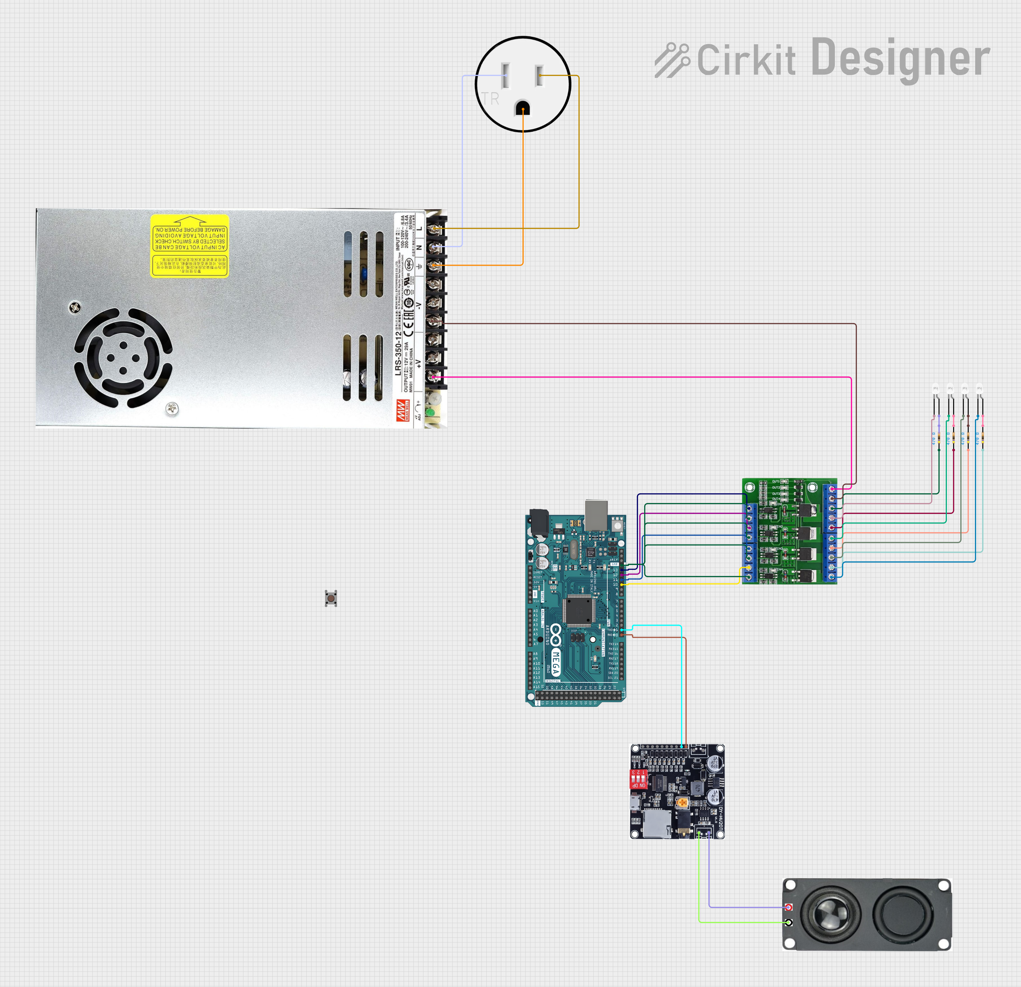
This document provides a detailed overview of a circuit that includes an Arduino Mega 2560 microcontroller, a ME60N03 4-Channel Mosfet, multiple LEDs with current-limiting resistors, a DY-HV20T audio module connected to an 8 Ohm 20W speaker, a DC power supply, and a 120V outlet for power input. The circuit is designed to control the LEDs via PWM signals from the Arduino and to communicate with the DY-HV20T module for audio output.
Component List
Microcontroller
- Arduino Mega 2560: A microcontroller board based on the ATmega2560 with numerous digital and analog I/O pins.
Mosfet
- ME60N03 4-Channel Mosfet: A 4-channel MOSFET module used for switching high current loads with PWM control from the Arduino.
LEDs
- LED: Two Pin (white): White LEDs used for lighting or indication purposes.
Resistors
- Resistor: 470 Ohm resistors used to limit the current through the LEDs to safe levels.
Power Supply
- DC POWER SUPPLY: Provides +12VDC and GND to power the circuit.
Audio Module
- DY-HV20T: An audio module capable of playing stored sounds, connected to the Arduino for control and to a speaker for audio output.
Speaker
- 8 OHM 20W SPEAKER: A speaker connected to the DY-HV20T for audio playback.
Outlet
- 120V Outlet: Provides 120VAC power to the DC power supply.
Pushbutton
- Pushbutton: A momentary pushbutton switch, not detailed in the wiring list but included in the component list.
Wiring Details
Arduino Mega 2560
- Connected to DY-HV20T for serial communication (TX0, RX0).
- Connected to ME60N03 4-Channel Mosfet for PWM control (D10, D11, D12, D13).
- Ground connected to ME60N03 4-Channel Mosfet.
ME60N03 4-Channel Mosfet
- PWM inputs connected to Arduino Mega 2560.
- Power supply inputs (+12VDC, GND) connected to DC POWER SUPPLY.
- Outputs connected to LEDs through current-limiting resistors.
LEDs
- Each LED has its cathode connected to the corresponding Mosfet output and anode connected to a 470 Ohm resistor.
Resistors
- Each 470 Ohm resistor is connected between the anode of an LED and the corresponding Mosfet output.
DC POWER SUPPLY
- +12VDC and GND outputs connected to ME60N03 4-Channel Mosfet.
- 120VAC inputs connected to 120V Outlet.
DY-HV20T
- Serial communication with Arduino Mega 2560 (TXD, RXD).
- Speaker outputs connected to 8 OHM 20W SPEAKER.
8 OHM 20W SPEAKER
- Connected to DY-HV20T for audio output.
120V Outlet
- Provides AC power to DC POWER SUPPLY.
Documented Code
Arduino Mega 2560 Code (sketch.ino)
void setup() {
  // put your setup code here, to run once:

}

void loop() {
  // put your main code here, to run repeatedly:

}
Note: The provided code is a template and does not contain any functional code. It needs to be populated with the logic to control the PWM outputs and handle serial communication with the DY-HV20T module.