Arduino Uno R3 Controlled Ultrasonic Distance Detection with Relay-Driven DC Motor
Circuit Documentation
Summary
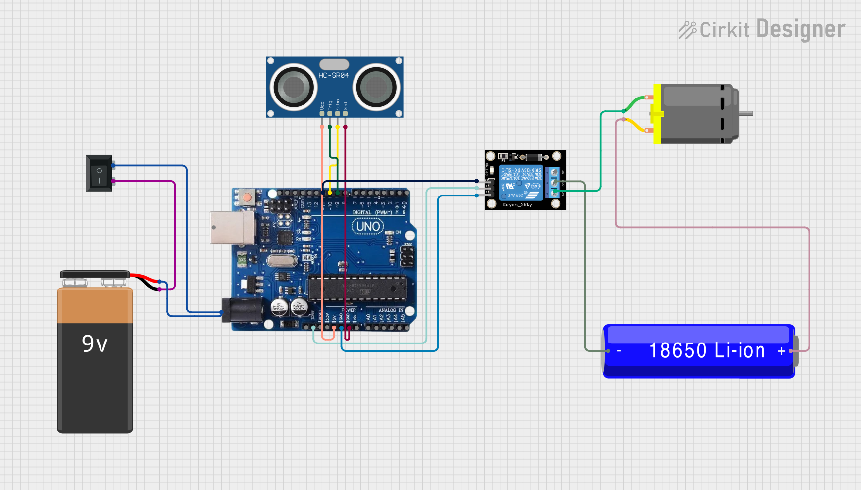
This circuit is designed to control a DC motor using an Arduino Uno R3 microcontroller in conjunction with a relay module and an HC-SR04 ultrasonic sensor. The motor is powered by an 18650 Li-ion battery and is switched on and off based on the proximity of an object detected by the ultrasonic sensor. A 9V battery powers the Arduino, and a rocker switch is used to control the power supply to the Arduino.
Component List
Arduino Uno R3
- Microcontroller board based on the ATmega328P
- It has 14 digital input/output pins, 6 analog inputs, a USB connection, a power jack, an ICSP header, and a reset button.
Relay Module 1 Channel
- A module that can be used to control high power/high voltage devices safely.
- It has a single channel and can be driven by the Arduino to switch devices on and off.
HC-SR04 Ultrasonic Sensor
- An ultrasonic distance sensor that can measure distances from 2cm to 400cm with an accuracy of 3mm.
- It has four pins: VCC, TRIG, ECHO, and GND.
DC Motor
- A simple electric motor that converts electrical energy into mechanical energy.
- It has two pins for connecting to a power source.
18650 Li-ion Battery
- A rechargeable battery that provides a power source for the DC motor.
- It has a positive and a negative terminal.
9V Battery
- A standard 9V battery used to power the Arduino Uno R3.
- It has a positive and a negative terminal.
Rocker Switch (SPST)
- A single pole single throw (SPST) switch used to control the power supply to the Arduino Uno R3.
- It has two terminals for connecting the power source and the load.
Wiring Details
Arduino Uno R3
- Power Jack connected to the positive terminal of the 9V Battery through the Rocker Switch (SPST).
- IOREF connected to the 5V pin of the Relay Module.
- 5V connected to the VCC pin of the HC-SR04 Ultrasonic Sensor.
- GND connected to the GND pin of the Relay Module and the GND pin of the HC-SR04 Ultrasonic Sensor.
- Pin 11 (relayPin) connected to the S pin of the Relay Module.
- Pin 10 (echoPin) connected to the ECHO pin of the HC-SR04 Ultrasonic Sensor.
- Pin 9 (trigPin) connected to the TRIG pin of the HC-SR04 Ultrasonic Sensor.
Relay Module 1 Channel
- 5V connected to the IOREF pin of the Arduino Uno R3.
- GND connected to the GND pin of the Arduino Uno R3.
- S connected to pin 11 of the Arduino Uno R3.
- COM connected to the negative terminal of the 18650 Li-ion Battery.
- NO connected to pin 1 of the DC Motor.
HC-SR04 Ultrasonic Sensor
- VCC connected to the 5V pin of the Arduino Uno R3.
- TRIG connected to pin 9 of the Arduino Uno R3.
- ECHO connected to pin 10 of the Arduino Uno R3.
- GND connected to the GND pin of the Arduino Uno R3.
DC Motor
- Pin 1 connected to the NO pin of the Relay Module.
- Pin 2 connected to the positive terminal of the 18650 Li-ion Battery.
18650 Li-ion Battery
- Positive terminal connected to pin 2 of the DC Motor.
- Negative terminal connected to the COM pin of the Relay Module.
9V Battery
- Positive terminal connected to the Power Jack of the Arduino Uno R3 through the Rocker Switch (SPST).
- Negative terminal connected to terminal 2 of the Rocker Switch (SPST).
Rocker Switch (SPST)
- Terminal 1 connected to the positive terminal of the 9V Battery.
- Terminal 2 connected to the negative terminal of the 9V Battery and the Power Jack of the Arduino Uno R3.
Documented Code
#define trigPin 9
#define echoPin 10
#define relayPin 11

void setup() {
  pinMode(trigPin, OUTPUT);
  pinMode(echoPin, INPUT);
  pinMode(relayPin, OUTPUT);

  // Set the relay pin to HIGH by default to keep the motor off initially
  digitalWrite(relayPin, HIGH);

  Serial.begin(9600);
}

void loop() {
  long duration, distance;

  // Send the ultrasonic pulse
  digitalWrite(trigPin, LOW);
  delayMicroseconds(2);
  digitalWrite(trigPin, HIGH);
  delayMicroseconds(10);
  digitalWrite(trigPin, LOW);

  // Read the echo time
  duration = pulseIn(echoPin, HIGH);

  // Calculate distance in cm
  distance = (duration / 2) / 29.1;

  // If an object is within 10 cm, turn on the fan
  if (distance <= 10) {
    digitalWrite(relayPin, LOW);  // Activate the relay (assuming it's active LOW), turning on the fan
  } else {
    digitalWrite(relayPin, HIGH);  // Deactivate the relay, turning off the fan
  }

  // Print the distance to the serial monitor
  Serial.print("Distance: ");
  Serial.print(distance);
  Serial.println(" cm");

  delay(100);  // Small delay for stability
}
The code is written for the Arduino Uno R3 and is responsible for controlling the relay module based on the distance measured by the HC-SR04 ultrasonic sensor. The relay, in turn, controls the power to the DC motor. When an object is detected within 10 cm of the sensor, the motor is turned on; otherwise, it remains off. The distance is also printed to the serial monitor for debugging purposes.