
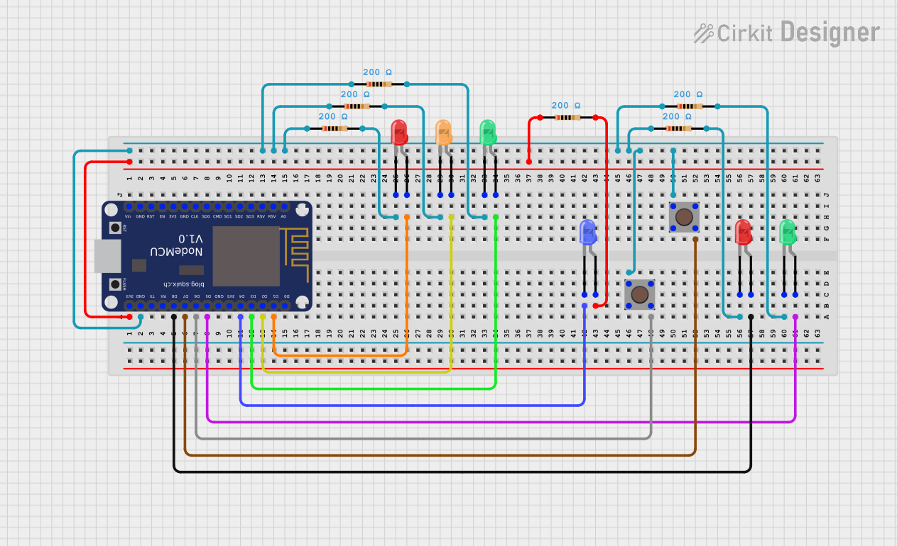
Circuit Documentation
Summary
This circuit is designed to control multiple LEDs using an ESP8266 microcontroller. The ESP8266 is responsible for switching individual LEDs on and off. The LEDs are of various colors: red, green, orange, and blue. Each LED is connected to the ESP8266 through a current-limiting resistor to protect the LED from excessive current. Additionally, there are switches in the circuit that may be used to control the flow of power or to trigger certain actions when interfaced with the ESP8266.
Component List
LEDs
- LED (Red): A two-pin red LED.
- LED (Green): A two-pin green LED.
- LED (Orange): A two-pin orange LED.
- LED (Blue): A two-pin blue LED.
Microcontroller
- ESP8266: A Wi-Fi capable microcontroller with multiple digital pins for controlling devices like LEDs.
Switches
- Switch: A simple two-pin switch used to open or close the electrical circuit.
Resistors
- Resistor (200 Ohms): A resistor with a resistance of 200 Ohms, used for current limiting to the LEDs.
Wiring Details
LEDs
LED (Red)
- Anode: Connected to a digital pin on the ESP8266.
- Cathode: Connected to one end of a 200 Ohm resistor.
LED (Green)
- Anode: Connected to a digital pin on the ESP8266.
- Cathode: Connected to one end of a 200 Ohm resistor.
LED (Orange)
- Anode: Connected to a digital pin on the ESP8266.
- Cathode: Connected to one end of a 200 Ohm resistor.
LED (Blue)
- Anode: Connected to a digital pin on the ESP8266.
- Cathode: Connected to one end of a 200 Ohm resistor.
Microcontroller
- ESP8266
- 3V3: Connected to one end of a 200 Ohm resistor.
- GND: Connected to the common ground net, which includes the ground side of switches and resistors.
- Digital Pins (D0, D1, D2, D3, D4, D5, D6, D7, D8): Connected to the anodes of LEDs or the second pin of switches.
Switches
- Switch
- Pin 1: Connected to the ground net.
- Pin 2: Connected to a digital pin on the ESP8266.
Resistors
- Resistor (200 Ohms)
- Pin 1: Connected to either the 3V3 pin on the ESP8266 or the cathode of an LED.
- Pin 2: Connected to either the ground net or the anode of an LED.
Documented Code
No code has been provided for the microcontroller. The expected behavior would be to initialize the digital pins connected to the LEDs as outputs and then to control them by setting the pins high or low, depending on the desired state of the LEDs. The switches would likely be set up as inputs with either internal or external pull-up or pull-down resistors to ensure a stable state when the switch is open.