
Arduino UNO Based Temperature and Humidity Display with DHT11 and LCD
View and Edit Project In Cirkit Designer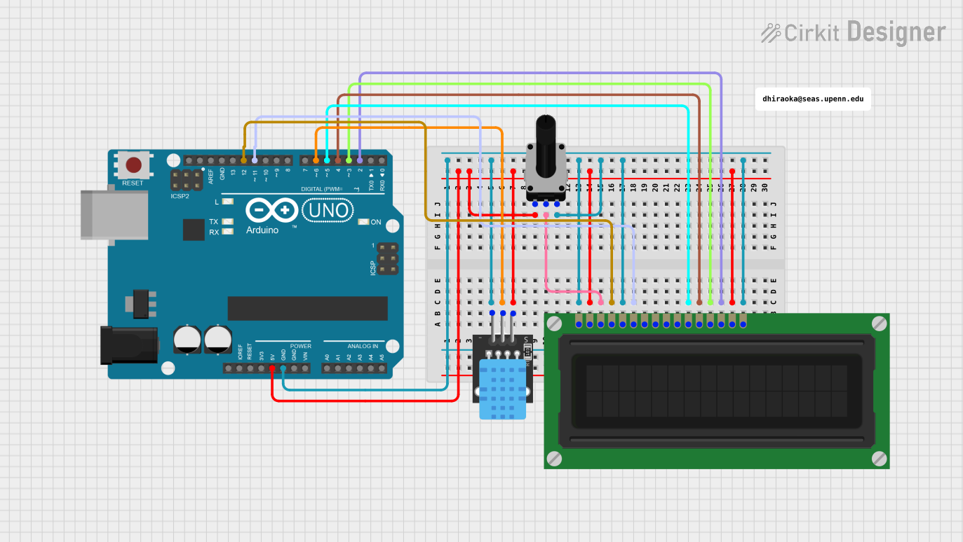
Circuit Documentation
Summary
This circuit is designed to interface a DHT11 temperature and humidity sensor with an Arduino UNO microcontroller, display the sensor readings on an LCD display, and adjust the display contrast using a rotary potentiometer. The Arduino UNO reads the sensor data and controls the LCD to update the temperature and humidity values periodically.
Component List
DHT11
- Description: A digital temperature and humidity sensor.
- Pins: 5V (Power), S (Signal), GND (Ground).
LCD Display (16 pin)
- Description: A 16x2 character LCD display for showing information.
- Pins: VSS (Ground), VDD (Power), VO (Contrast), RS (Register Select), R/W (Read/Write), E (Enable), DB0-DB7 (Data Bus), A (Anode for Backlight), K (Cathode for Backlight).
Rotary Potentiometer
- Description: A variable resistor used to adjust the LCD contrast.
- Pins: leg1 (One end of the resistor), wiper (Variable tap), leg2 (Other end of the resistor).
- Properties: Resistance - 10,000 Ohms.
Arduino UNO
- Description: A microcontroller board based on the ATmega328P.
- Pins: Digital I/O Pins (D0-D13), Analog Input Pins (A0-A5), Power Pins (3.3V, 5V, GND, Vin), I2C Pins (SCL, SDA), SPI Pins (AREF, Reset), and others not used in this circuit.
Comment
- Description: A placeholder for additional notes or comments.
Wiring Details
DHT11
- 5V: Connected to the 5V power supply from the Arduino UNO.
- S: Signal pin connected to Digital Pin 6 (D6) on the Arduino UNO.
- GND: Ground connected to the common ground net in the circuit.
LCD Display (16 pin)
- VSS: Connected to the common ground net in the circuit.
- VDD: Connected to the 5V power supply from the Arduino UNO.
- VO: Contrast adjustment connected to the wiper of the rotary potentiometer.
- RS: Register Select connected to Digital Pin 12 (D12) on the Arduino UNO.
- R/W: Read/Write pin grounded (write mode).
- E: Enable pin connected to Digital Pin 11 (D11) on the Arduino UNO.
- DB4-DB7: Data bus pins connected to Digital Pins 5 (D5), 4 (D4), 3 (D3), and 2 (D2) on the Arduino UNO respectively.
- A: Anode for backlight connected to the 5V power supply from the Arduino UNO.
- K: Cathode for backlight connected to the common ground net in the circuit.
Rotary Potentiometer
- leg1: Connected to the 5V power supply from the Arduino UNO.
- wiper: Connected to the VO pin on the LCD display for contrast adjustment.
- leg2: Connected to the common ground net in the circuit.
Documented Code
#include <LiquidCrystal.h>
#include <DHT.h>

// Initialize the LCD library with the numbers of the interface pins
LiquidCrystal lcd(12, 11, 5, 4, 3, 2);

// Define the DHT11 sensor pin and type
#define DHTPIN 6
#define DHTTYPE DHT11

// Initialize the DHT sensor
DHT dht(DHTPIN, DHTTYPE);

void setup() {
  // Set up the LCD's number of columns and rows
  lcd.begin(16, 2);

  // Initialize the DHT sensor
  dht.begin();

  // Print a message to the LCD
  lcd.print("Temp: ");
  lcd.setCursor(0, 1);
  lcd.print("Humidity: ");
}

void loop() {
  // Read temperature and humidity from the DHT11 sensor
  float h = dht.readHumidity();
  float t = dht.readTemperature();

  // Check if any reads failed and exit early (to try again)
  if (isnan(h) || isnan(t)) {
    lcd.setCursor(6, 0);
    lcd.print("Error");
    lcd.setCursor(10, 1);
    lcd.print("Error");
    return;
  }

  // Print the temperature to the LCD
  lcd.setCursor(6, 0);
  lcd.print(t);
  lcd.print(" C");

  // Print the humidity to the LCD
  lcd.setCursor(10, 1);
  lcd.print(h);
  lcd.print(" %");

  // Wait a few seconds between measurements
  delay(2000);
}
This code is responsible for initializing the LCD and DHT11 sensor, reading temperature and humidity data from the DHT11, and displaying the values on the LCD. If the sensor fails to provide valid readings, an error message is displayed. The LCD contrast can be adjusted using the rotary potentiometer.