
Arduino UNO-Based Smart Security System with PIR Sensor and LCD Display
View and Edit Project In Cirkit Designer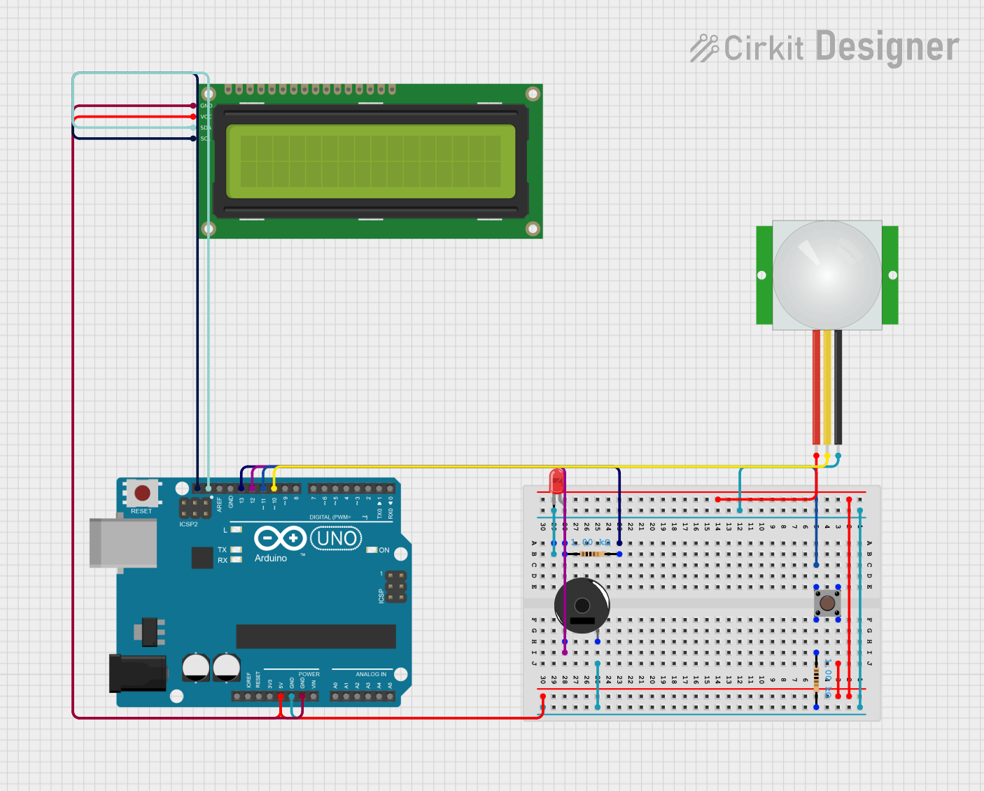
Circuit Documentation
Summary
This circuit is designed to detect motion using a PIR sensor and display the system status on a 16x2 I2C LCD. It also includes a pushbutton to toggle the system state, an LED to indicate motion detection, and a piezo buzzer to sound an alarm when motion is detected. The circuit is controlled by an Arduino UNO microcontroller.
Component List
Arduino UNO
- Description: Microcontroller board based on the ATmega328P.
- Pins: UNUSED, IOREF, Reset, 3.3V, 5V, GND, Vin, A0, A1, A2, A3, A4, A5, SCL, SDA, AREF, D13, D12, D11, D10, D9, D8, D7, D6, D5, D4, D3, D2, D1, D0
LED: Two Pin (red)
- Description: A red LED with two pins.
- Pins: cathode, anode
Resistor (1k Ohms)
- Description: A resistor with a resistance of 1000 Ohms.
- Pins: pin1, pin2
Piezo Buzzer
- Description: A piezoelectric buzzer.
- Pins: pin 1, pin 2
Pushbutton
- Description: A pushbutton switch.
- Pins: Pin 3 (out), Pin 4 (out), Pin 1 (in), Pin 2 (in)
PIR sensor
- Description: A passive infrared sensor for motion detection.
- Pins: VDD, SIG, GND
16x2 I2C LCD
- Description: A 16x2 character LCD with I2C interface.
- Pins: GND, VCC, SDA, SCL
Wiring Details
Arduino UNO
- 5V: Connected to VCC of 16x2 I2C LCD, Pin 4 (out) of Pushbutton, and VDD of PIR sensor.
- GND: Connected to GND of 16x2 I2C LCD, pin2 of Resistor (1k Ohms), pin 2 of Piezo Buzzer, GND of PIR sensor, and cathode of LED.
- SCL: Connected to SCL of 16x2 I2C LCD.
- SDA: Connected to SDA of 16x2 I2C LCD.
- D13: Connected to pin2 of Resistor (1k Ohms).
- D12: Connected to pin 1 of Piezo Buzzer.
- D11: Connected to Pin 1 (in) of Pushbutton.
- D10: Connected to SIG of PIR sensor.
LED: Two Pin (red)
- cathode: Connected to GND of Arduino UNO.
- anode: Connected to pin1 of Resistor (1k Ohms).
Resistor (1k Ohms)
- pin1: Connected to anode of LED and Pin 2 (in) of Pushbutton.
- pin2: Connected to GND of Arduino UNO and D13 of Arduino UNO.
Piezo Buzzer
- pin 1: Connected to D12 of Arduino UNO.
- pin 2: Connected to GND of Arduino UNO.
Pushbutton
- Pin 1 (in): Connected to D11 of Arduino UNO.
- Pin 2 (in): Connected to pin1 of Resistor (1k Ohms).
- Pin 3 (out): Not connected.
- Pin 4 (out): Connected to 5V of Arduino UNO.
PIR sensor
- VDD: Connected to 5V of Arduino UNO.
- SIG: Connected to D10 of Arduino UNO.
- GND: Connected to GND of Arduino UNO.
16x2 I2C LCD
- GND: Connected to GND of Arduino UNO.
- VCC: Connected to 5V of Arduino UNO.
- SDA: Connected to SDA of Arduino UNO.
- SCL: Connected to SCL of Arduino UNO.
Documented Code
#include <Adafruit_LiquidCrystal.h>

Adafruit_LiquidCrystal lcd(0);
int led = 13;
int buzzer = 12;
int button = 11;
int holder = 0;
int pir = 10;
int pirholder = 0;

void setup() {
  // put your setup code here, to run once:
  pinMode(led, OUTPUT);
  pinMode(buzzer, OUTPUT);
  pinMode(pir, INPUT);
  pinMode(button, INPUT);
  lcd.begin(16, 2);
  lcd.print("is system on");
}

void loop() {
  // put your main code here, to run repeatedly:
  holder = digitalRead(button);
  pirholder = digitalRead(pir);
  lcd.clear();
  lcd.setCursor(0, 0);

  if (holder == 1) {
    if (pirholder == 1) {
      digitalWrite(led, HIGH);
      delay(200);
      digitalWrite(buzzer, HIGH);
      delay(10000);
      digitalWrite(led, LOW);
      digitalWrite(buzzer, LOW);
    } else {
      lcd.clear();
      lcd.print("NO one inside the building");
    }
  } else {
    lcd.clear();
    lcd.print("System is off");
  }
}
This code initializes the components and continuously checks the state of the pushbutton and PIR sensor. If the button is pressed and motion is detected, the LED and buzzer are activated. The LCD displays the system status accordingly.