
STM32F103C8T6 Microcontroller-Based Motor Control System with RS485 Communication
View and Edit Project In Cirkit Designer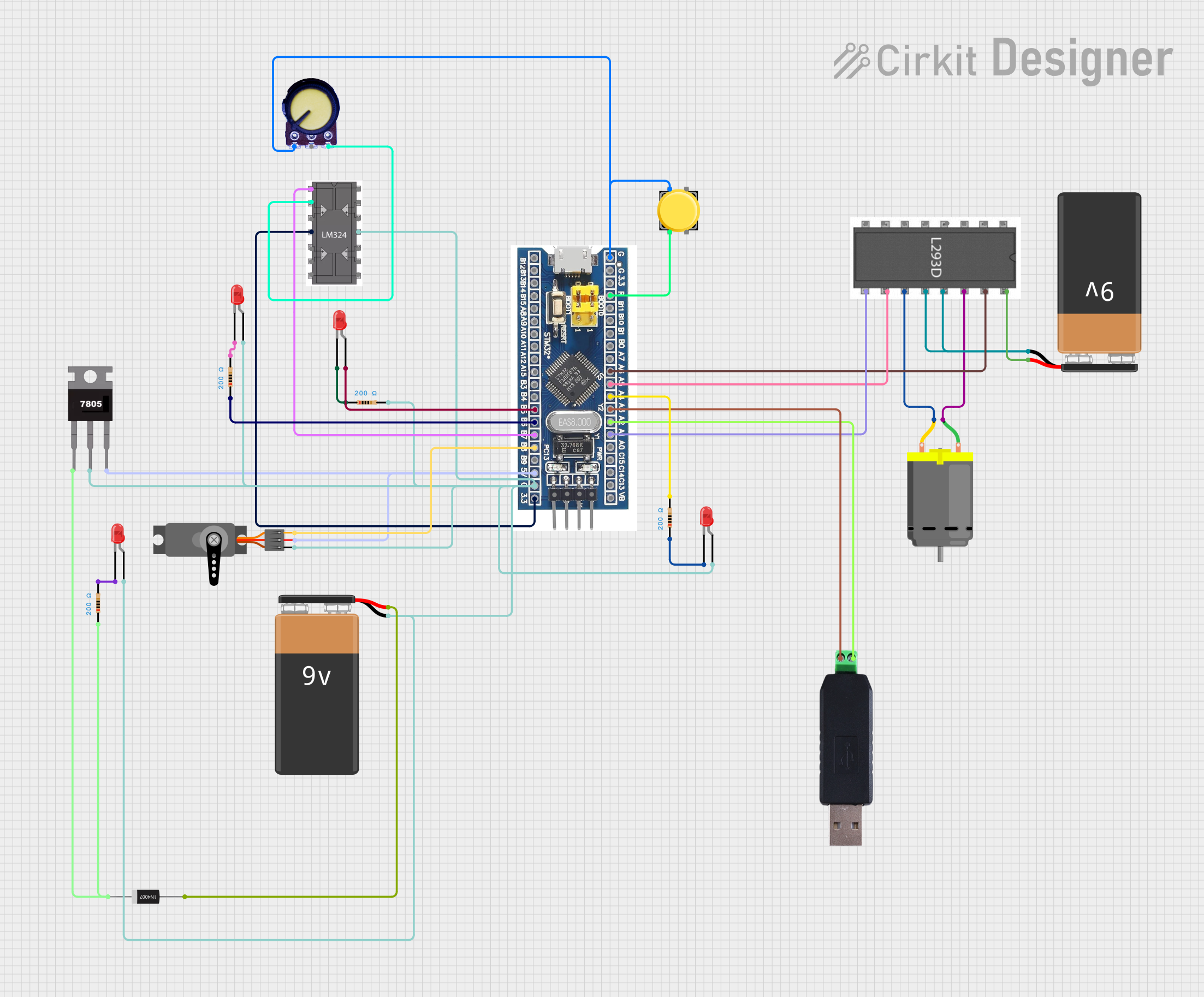
Circuit Documentation
Summary
The circuit in question appears to be a complex system involving power management, signal processing, and actuator control. It includes a microcontroller (STM32F103C8T6), multiple LEDs, a motor driver (l293d), voltage regulation components (7805 and 1N4007 diode), a DC motor, a servo motor, a communication module (RS485 to USB Converter), and various passive components such as resistors, a potentiometer, and a pushbutton. The circuit is powered by two 9V batteries. The microcontroller is likely the central processing unit, interfacing with the motor driver to control the DC motor, driving the servo motor, and managing communication through the RS485 to USB converter. The LEDs serve as indicators, and the resistors are used for current limiting and pull-up/pull-down configurations.
Component List
Active Components
- STM32F103C8T6 Microcontroller: A 32-bit microcontroller with a variety of I/O pins for interfacing with other components.
- l293d Motor Driver: A quadruple high-current half-H driver designed to provide bidirectional drive currents for motors.
- 7805 Voltage Regulator: A fixed-voltage integrated circuit voltage regulator providing a regulated 5V output.
- lm324 Operational Amplifier: A quadruple operational amplifier for signal processing tasks.
- RS485 to USB Converter: A communication module for converting RS485 signals to USB interface.
Passive Components
- LED (Red): A two-pin light-emitting diode used as an indicator.
- Resistor: A passive two-terminal electrical component that implements electrical resistance as a circuit element.
- 1N4007 Rectifier Diode: A high-voltage, high-current rectifier diode used for voltage regulation and protection.
- Pushbutton: A simple switch mechanism for controlling some aspect of a machine or a process.
- Potentiometer: A three-terminal resistor with a sliding or rotating contact that forms an adjustable voltage divider.
Power Supply
- 9V Battery: A standard 9V battery used to provide power to the circuit.
Actuators
- DC Motor: An electric motor driven by direct current (DC).
- Servo: A rotary actuator or linear actuator that allows for precise control of angular or linear position.
Wiring Details
STM32F103C8T6 Microcontroller
- GND connected to the anodes of multiple LEDs, ground of the servo, and ground of the lm324.
- 3.3V connected to VCC of the lm324.
- 5V connected to VCC of the servo and Vout of the 7805 voltage regulator.
- A1 connected to Enable 3,4 of the l293d motor driver.
- A2 connected to B/RX of the RS485 to USB Converter.
- A3 connected to A/TX of the RS485 to USB Converter.
- A4 connected to a resistor.
- A5 connected to Input 3 of the l293d motor driver.
- A6 connected to Input 4 of the l293d motor driver.
- B5 connected to the anode of an LED.
- B6 connected to a resistor.
- B7 connected to out1 of the lm324.
- B8 connected to PWM of the servo.
- reset connected to Pin 2 of the pushbutton.
LEDs (Red)
- Cathode of one LED connected to a resistor.
- Anode of the same LED connected to GND of the microcontroller.
- Cathode of another LED connected to a resistor.
- Anode of the same LED connected to GND of the microcontroller.
l293d Motor Driver
- GND connected to the negative terminal of a 9V battery.
- Vcc1 connected to the positive terminal of a 9V battery.
- Input 3 connected to A5 of the microcontroller.
- Input 4 connected to A6 of the microcontroller.
- Output 3 connected to pin 2 of the DC Motor.
- Output 4 connected to pin 1 of the DC Motor.
7805 Voltage Regulator
- Vin connected to the anode of the 1N4007 diode.
- Gnd connected to the anode of multiple LEDs and GND of the microcontroller.
- Vout connected to 5V of the microcontroller.
lm324 Operational Amplifier
- GND connected to the anode of multiple LEDs and GND of the microcontroller.
- VCC connected to 3.3V of the microcontroller.
- out1 connected to B7 of the microcontroller.
DC Motor
- Pin 1 connected to Output 4 of the l293d motor driver.
- Pin 2 connected to Output 3 of the l293d motor driver.
RS485 to USB Converter
- A/TX connected to A3 of the microcontroller.
- B/RX connected to A2 of the microcontroller.
Servo
- GND connected to the anode of multiple LEDs and GND of the microcontroller.
- VCC connected to 5V of the microcontroller.
- PWM connected to B8 of the microcontroller.
1N4007 Rectifier Diode
- Anode connected to the positive terminal of a 9V battery.
- Cathode connected to Vin of the 7805 voltage regulator and a resistor.
Resistor
- One end connected to various components such as LEDs, the microcontroller, and the diode.
- The other end connected to various components such as LEDs, the microcontroller, and the diode.
Pushbutton
- Pin 1 connected to GND of the microcontroller and GND of the potentiometer.
- Pin 2 connected to reset of the microcontroller.
Potentiometer
- GND connected to Pin 1 of the pushbutton.
- VCC connected to - in 1 of the lm324.
Documented Code
No code was provided for the microcontroller or any other programmable components in the circuit. Therefore, this section is left blank until the relevant code is made available.