
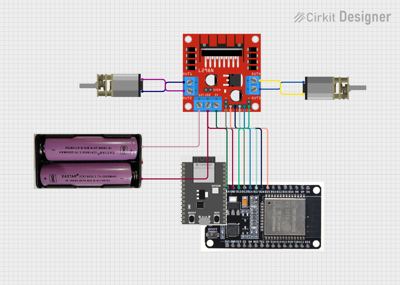
Circuit Documentation
Summary
This circuit is designed to control two DC motors using an ESP32 microcontroller and an L298N DC motor driver. The ESP32 microcontroller is programmed to gradually increase and decrease the speed of the motors in a loop. The motors are powered by a 7.4V power source, and the L298N motor driver interfaces between the ESP32 and the motors to control their direction and speed.
Component List
ESP32 Microcontroller
- Description: A microcontroller with Wi-Fi and Bluetooth capabilities, used for controlling the motors through the L298N driver.
- Pins: EN, VP, VN, D34, D35, D32, D33, D25, D26, D27, D14, D12, D13, GND, VIN, 3V3, D15, D2, D4, RX2, TX2, D5, D18, D19, D21, RX0, TX0, D22, D23, BOOT
L298N DC Motor Driver
- Description: A motor driver module capable of driving two DC motors, receiving control signals from the ESP32.
- Pins: OUT1, OUT2, 12V, GND, 5V, OUT3, OUT4, 5V-ENA-JMP-I, 5V-ENA-JMP-O, +5V-J1, +5V-J2, ENA, IN1, IN2, IN3, IN4, ENB
DC Mini Metal Gear Motor (x2)
- Description: Small DC motors with metal gears, controlled by the L298N driver.
- Pins: IN1, IN2
7.4V Power Source
- Description: Provides power to the circuit.
- Pins: +, -
ESP32-C3-DevKitM-1
- Description: A secondary microcontroller not directly involved in motor control.
- Pins: GND, 3V3, GPIO2, GPIO3, RST, GPIO0, GPIO1, GPIO10, 5V0, GPIO19, GPIO18, GPIO4, GPIO5, GPIO6, GPIO7, GPIO8, GPIO9, GPIO20, GPIO21
Wiring Details
ESP32 Microcontroller
- D25 connected to L298N IN1
- D26 connected to L298N IN2
- D27 connected to L298N IN3
- D14 connected to L298N IN4
- D12 connected to L298N ENA
- D13 connected to L298N ENB
- GND connected to L298N GND and 7.4V Power Source (-)
- VIN connected to L298N 5V
L298N DC Motor Driver
- OUT1 connected to DC Mini Metal Gear Motor (Motor 1) IN1
- OUT2 connected to DC Mini Metal Gear Motor (Motor 1) IN2
- OUT3 connected to DC Mini Metal Gear Motor (Motor 2) IN1
- OUT4 connected to DC Mini Metal Gear Motor (Motor 2) IN2
- 12V connected to 7.4V Power Source (+)
DC Mini Metal Gear Motor (Motor 1)
- IN1 connected to L298N OUT1
- IN2 connected to L298N OUT2
DC Mini Metal Gear Motor (Motor 2)
- IN1 connected to L298N OUT3
- IN2 connected to L298N OUT4
7.4V Power Source
- (+) connected to L298N 12V
- (-) connected to ESP32 GND
Documented Code
/*
 * This Arduino Sketch controls two DC motors connected to an L298N motor driver
 * using an ESP32 microcontroller. The motors will be slowly turned on and off
 * in a loop.
 */

// Define motor control pins
const int motor1Pin1 = 25;
const int motor1Pin2 = 26;
const int motor2Pin1 = 27;
const int motor2Pin2 = 14;
const int enable1Pin = 12;
const int enable2Pin = 13;

void setup() {
  // Set all the motor control pins to outputs
  pinMode(motor1Pin1, OUTPUT);
  pinMode(motor1Pin2, OUTPUT);
  pinMode(motor2Pin1, OUTPUT);
  pinMode(motor2Pin2, OUTPUT);
  pinMode(enable1Pin, OUTPUT);
  pinMode(enable2Pin, OUTPUT);

  // Initialize motors to be off
  digitalWrite(motor1Pin1, LOW);
  digitalWrite(motor1Pin2, LOW);
  digitalWrite(motor2Pin1, LOW);
  digitalWrite(motor2Pin2, LOW);
  analogWrite(enable1Pin, 0);
  analogWrite(enable2Pin, 0);
}

void loop() {
  // Slowly turn on motor 1
  for (int speed = 0; speed <= 255; speed++) {
    analogWrite(enable1Pin, speed);
    digitalWrite(motor1Pin1, HIGH);
    digitalWrite(motor1Pin2, LOW);
    delay(20);
  }

  // Slowly turn off motor 1
  for (int speed = 255; speed >= 0; speed--) {
    analogWrite(enable1Pin, speed);
    delay(20);
  }

  // Slowly turn on motor 2
  for (int speed = 0; speed <= 255; speed++) {
    analogWrite(enable2Pin, speed);
    digitalWrite(motor2Pin1, HIGH);
    digitalWrite(motor2Pin2, LOW);
    delay(20);
  }

  // Slowly turn off motor 2
  for (int speed = 255; speed >= 0; speed--) {
    analogWrite(enable2Pin, speed);
    delay(20);
  }
}
This code is designed to run on the ESP32 microcontroller and controls the speed and direction of two DC motors via the L298N motor driver. The setup() function initializes the motor control pins and sets the motors to be off. The loop() function contains two for-loops that gradually increase and decrease the PWM signal to the enable pins, which controls the speed of the motors. The motors are set to move in one direction by setting one control pin to HIGH and the other to LOW.