
Arduino 101-Based Smart Environmental Monitoring System with Bluetooth Connectivity
View and Edit Project In Cirkit Designer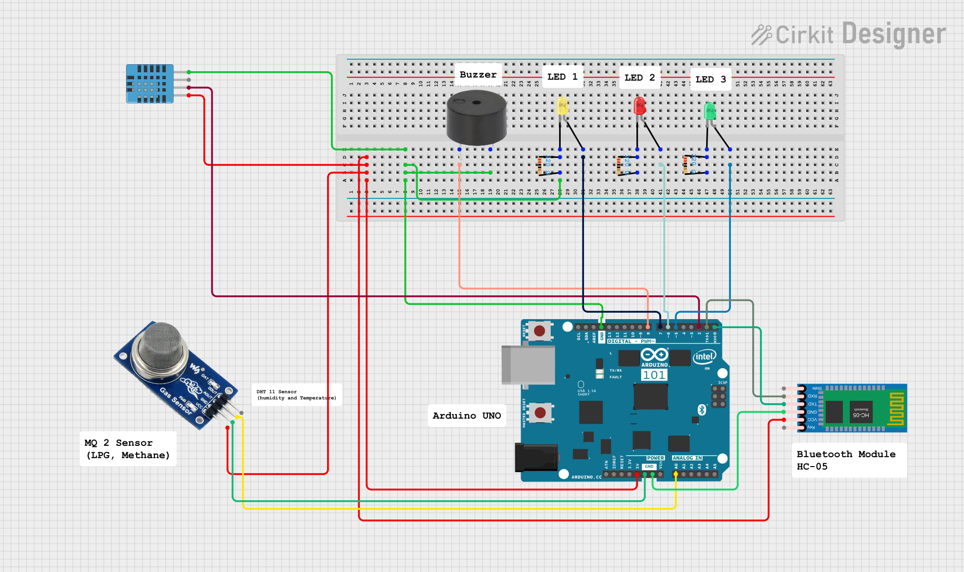
Circuit Documentation
Summary
This circuit is designed to monitor environmental conditions using an MQ2 gas sensor and a DHT11 humidity and temperature sensor. It also includes an HC-05 Bluetooth module for wireless communication, a buzzer for alerts, and three LEDs (yellow, red, and green) for visual indicators. The circuit is controlled by an Arduino 101 microcontroller.
Component List
MQ2 Gas Sensor
- Pins: VCC, GND, AOUT, DOUT
- Description: The MQ2 gas sensor is used to detect the presence of gases such as LPG, i-butane, propane, methane, alcohol, hydrogen, and smoke.
DHT11 Humidity and Temperature Sensor
- Pins: VDD, DATA, NULL, GND
- Description: The DHT11 sensor measures both humidity and temperature.
HC-05 Bluetooth Module
- Pins: Key, VCC, TXD, RXD, State, GND
- Description: The HC-05 module is used for wireless communication via Bluetooth.
Arduino 101
- Pins: A5/SCL, A4/SDA, AREF, GND, D13/SCK, D12/MISO, D11 PWM/MOSI, D10 PWM/SS, D9 PWM, D8, D7, D6 PWM, D5 PWM, D4, D3 PWM, D2, D1/TX, D0/RX, AIN, ioref, RESET, 3V3, 5V, VIN, A0, A1, A2, A3, ICSP MISO, ICSP SCK, ICSP MOSI
- Description: The Arduino 101 is the main microcontroller used to control the circuit and process sensor data.
Buzzer
- Pins: PIN, GND
- Description: The buzzer is used to provide audible alerts.
LED: Two Pin (Yellow)
- Pins: Cathode, Anode
- Description: A yellow LED used as a visual indicator.
LED: Two Pin (Red)
- Pins: Cathode, Anode
- Description: A red LED used as a visual indicator.
LED: Two Pin (Green)
- Pins: Cathode, Anode
- Description: A green LED used as a visual indicator.
Resistor (220 Ohms)
- Pins: Pin1, Pin2
- Description: Resistors used to limit current to the LEDs.
- Properties: Resistance: 220 Ohms
Wiring Details
MQ2 Gas Sensor
- VCC: Connected to Arduino 101 5V
- GND: Connected to Arduino 101 GND
- AOUT: Connected to Arduino 101 A0
DHT11 Humidity and Temperature Sensor
- VDD: Connected to Arduino 101 5V
- DATA: Connected to Arduino 101 D2
- GND: Connected to Arduino 101 GND
HC-05 Bluetooth Module
- VCC: Connected to Arduino 101 5V
- TXD: Connected to Arduino 101 D0/RX
- RXD: Connected to Arduino 101 D1/TX
- GND: Connected to Arduino 101 GND
Buzzer
- PIN: Connected to Arduino 101 D8
- GND: Connected to Arduino 101 GND
LED: Two Pin (Yellow)
- Anode: Connected to Arduino 101 D7
- Cathode: Connected to one end of a 220 Ohm resistor
- Resistor: Other end connected to Arduino 101 GND
LED: Two Pin (Red)
- Anode: Connected to Arduino 101 D6 PWM
- Cathode: Connected to one end of a 220 Ohm resistor
- Resistor: Other end connected to Arduino 101 GND
LED: Two Pin (Green)
- Anode: Connected to Arduino 101 D5 PWM
- Cathode: Connected to one end of a 220 Ohm resistor
- Resistor: Other end connected to Arduino 101 GND
Code Documentation
#include <DHT.h>

#define DHTPIN 2
#define DHTTYPE DHT11
#define BUZZER_PIN 8
#define ALERT_LED_PIN 7
#define CONTROL_LED_PIN 6
#define CONTROL_LED2_PIN 5
#define MQ2_PIN A0
#define THRESHOLD 600

DHT dht(DHTPIN, DHTTYPE);

void setup() {
    Serial.begin(9600);
    dht.begin();
    pinMode(BUZZER_PIN, OUTPUT);
    pinMode(ALERT_LED_PIN, OUTPUT);
    pinMode(CONTROL_LED_PIN, OUTPUT);
    pinMode(CONTROL_LED2_PIN, OUTPUT);
    Serial.println("Type 'on' or 'off' to control the first LED, and 'on2' or 'off2' for the second LED.");
}

void loop() {
    int mq2Value = analogRead(MQ2_PIN);
    if (mq2Value > THRESHOLD) {
        digitalWrite(BUZZER_PIN, HIGH);
        digitalWrite(ALERT_LED_PIN, HIGH);
    } else {
        digitalWrite(BUZZER_PIN, LOW);
        digitalWrite(ALERT_LED_PIN, LOW);
    }

    if (Serial.available() > 0) {
        String command = Serial.readStringUntil('\n');
        command.trim();
        if (command == "on") {
            digitalWrite(CONTROL_LED_PIN, HIGH);
            Serial.println("Control LED 1 turned ON");
        } else if (command == "off") {
            digitalWrite(CONTROL_LED_PIN, LOW);
            Serial.println("Control LED 1 turned OFF");
        } else if (command == "on2") {
            digitalWrite(CONTROL_LED2_PIN, HIGH);
            Serial.println("Control LED 2 turned ON");
        } else if (command == "off2") {
            digitalWrite(CONTROL_LED2_PIN, LOW);
            Serial.println("Control LED 2 turned OFF");
        } else {
            Serial.println("Invalid command. Type 'on', 'off', 'on2', or 'off2'.");
        }
    }

    float humidity = dht.readHumidity();
    float temperature = dht.readTemperature();
    if (isnan(humidity) || isnan(temperature)) {
        Serial.println("Failed to read from DHT sensor!");
    } else {
        Serial.print("Humidity: ");
        Serial.print(humidity);
        Serial.print("% Temperature: ");
        Serial.print(temperature);
        Serial.println("°C");
    }
}
This code initializes the DHT11 sensor, sets up the pins for the buzzer and LEDs, and continuously reads the gas sensor value. If the gas concentration exceeds a threshold, the buzzer and alert LED are activated. The code also listens for serial commands to control two additional LEDs and prints the humidity and temperature readings to the serial monitor.