
Arduino-Controlled Automated Watering System with Solar Charging
View and Edit Project In Cirkit Designer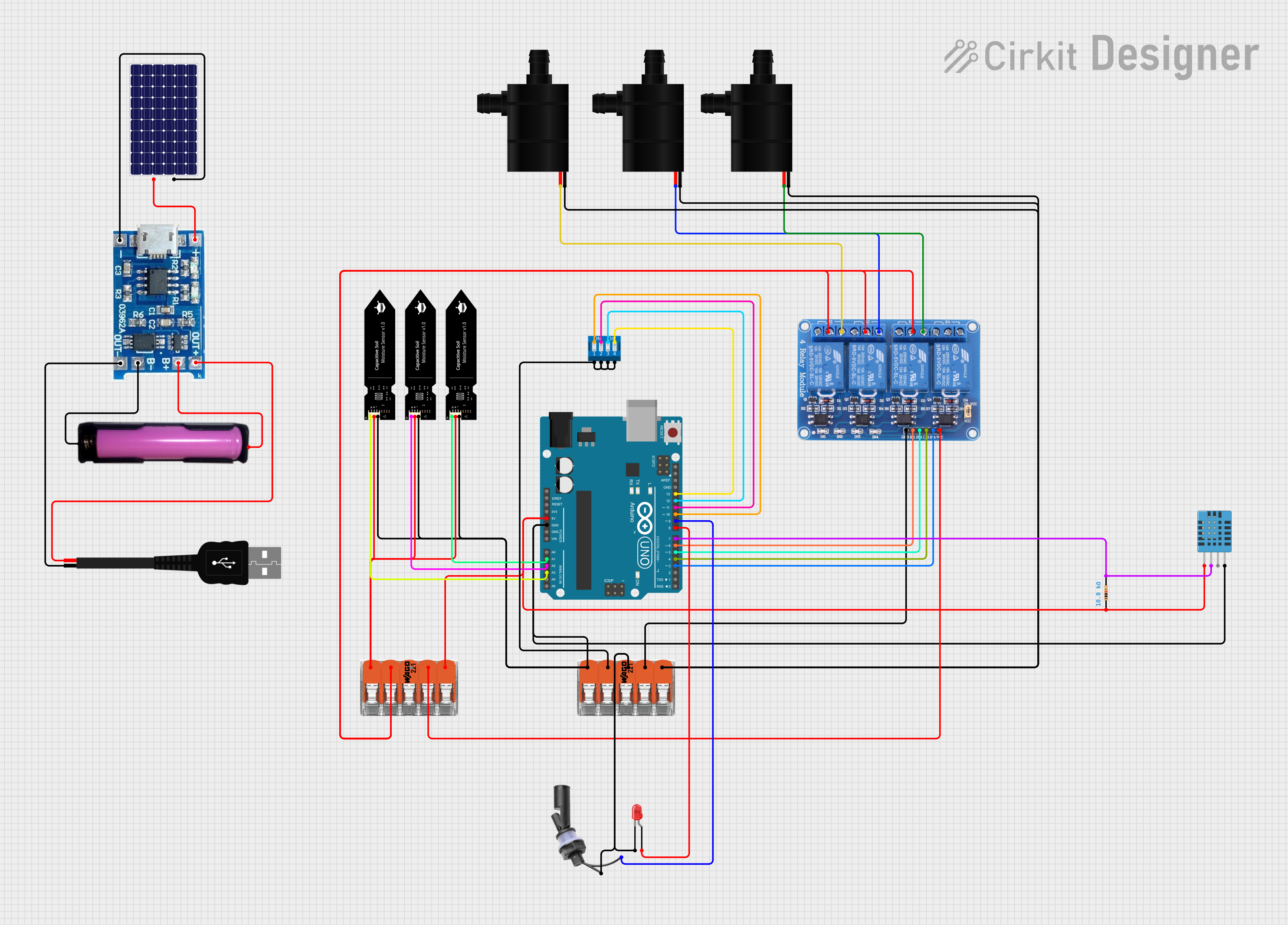
Circuit Documentation
Summary
This circuit is designed to control multiple water pumps based on sensor inputs, with power management through a solar panel and a battery. It includes an Arduino UNO microcontroller for logic control, relay modules for pump activation, soil moisture sensors for environmental feedback, a temperature and humidity sensor, and a water level float switch for monitoring water levels. The circuit is powered by a solar panel connected to a charge controller, which charges an 18650 battery and provides USB output for powering the system.
Component List
Relay 4 Channel 5v
- Description: A 4-channel relay module capable of controlling high power devices.
- Pins: GND, IN1, IN2, IN3, IN4, VCC, COM1, COM2, COM3, COM4, NO1, NO2, NO3, NO4, NC1, NC2, NC3, NC4
Solar Panel
- Description: A photovoltaic panel for converting solar energy into electrical power.
- Pins: +, -
18650 in Holder
- Description: A battery holder for an 18650 lithium-ion cell.
- Pins: GND, VCC
USB Male 2 Pin Connection
- Description: A USB connector for power input/output.
- Pins: Negative -, Positive +
Splicing Connector WAGO 221
- Description: A reusable splicing connector for joining multiple wires.
- Pins: Port 1, Port 2, Port 3, Port 4, Port 5
Water Pump
- Description: An electric pump for moving water.
- Pins: VCC, GND
DFRobot Capacitive Soil Moisture Sensor (V1.0)
- Description: A sensor for measuring the moisture level in soil.
- Pins: A, VCC, GND
Do Solar
- Description: A solar charge controller for managing power from a solar panel to a battery and load.
- Pins: -, +, out+, out-, b+, b-
LED: Two Pin (red)
- Description: A basic red LED.
- Pins: cathode, anode
Water Level Float Switch Sensor
- Description: A sensor for detecting the presence of water at a certain level.
- Pins: Wire2, Wire1
DIP Switch 4 Position
- Description: A 4-position DIP switch for setting binary configurations.
- Pins: 1, 2, 3, 4, 5, 6, 7, 8
DHT11 Humidity and Temperature Sensor
- Description: A sensor for measuring ambient temperature and humidity.
- Pins: VDD, DATA, NULL, GND
Arduino UNO
- Description: A microcontroller board based on the ATmega328P.
- Pins: UNUSED, IOREF, Reset, 3.3V, 5V, GND, Vin, A0, A1, A2, A3, A4, A5, SCL, SDA, AREF, D13, D12, D11, D10, D9, D8, D7, D6, D5, D4, D3, D2, D1, D0
Resistor
- Description: A passive two-terminal electrical component that implements electrical resistance as a circuit element.
- Properties: Resistance: 10000 Ohms
Wiring Details
Relay 4 Channel 5v
- GND connected to Splicing connector WAGO 221 (Port 2)
- IN1 connected to Arduino UNO (D6)
- IN2 connected to Arduino UNO (D5)
- IN3 connected to Arduino UNO (D4)
- IN4 connected to Arduino UNO (D3)
- VCC connected to Splicing connector WAGO 221 (Port 2)
- COM1, COM2, COM3 connected to Splicing connector WAGO 221 (Port 4)
- NO1 connected to Water Pump (VCC)
- NO2 connected to Water Pump (VCC)
- NO3 connected to Water Pump (VCC)
Solar Panel
-
- connected to Do Solar (+)
-
- connected to Do Solar (-)
18650 in Holder
- GND connected to Do Solar (b-)
- VCC connected to Do Solar (b+)
USB Male 2 Pin Connection
- Negative - connected to Do Solar (out-)
- Positive + connected to Do Solar (out+)
Splicing Connector WAGO 221
- Port 1 connected to Water Pump (GND)
- Port 2 connected to Relay 4 Channel 5v (GND) and (VCC)
- Port 3 connected to LED: Two Pin (red) (cathode) and Water Level Float Switch Sensor (Wire1)
- Port 4 connected to Relay 4 Channel 5v (COM1, COM2, COM3) and DIP Switch 4 Position (1, 2, 3, 4)
- Port 5 connected to DFRobot Capacitive Soil Moisture Sensor (VCC) and Arduino UNO (GND)
Water Pump
- GND connected to Splicing connector WAGO 221 (Port 1)
- VCC connected to Relay 4 Channel 5v (NO1, NO2, NO3)
DFRobot Capacitive Soil Moisture Sensor (V1.0)
- A connected to Arduino UNO (A1, A2, A3)
- VCC connected to Splicing connector WAGO 221 (Port 5)
- GND connected to Arduino UNO (GND)
Do Solar
-
- connected to Solar Panel (+)
-
- connected to Solar Panel (-)
- out+ connected to USB Male 2 Pin Connection (Positive +)
- out- connected to USB Male 2 Pin Connection (Negative -)
- b+ connected to 18650 in Holder (VCC)
- b- connected to 18650 in Holder (GND)
LED: Two Pin (red)
- cathode connected to Splicing connector WAGO 221 (Port 3)
- anode connected to Arduino UNO (D8)
Water Level Float Switch Sensor
- Wire1 connected to Splicing connector WAGO 221 (Port 3)
- Wire2 connected to Arduino UNO (D9)
DIP Switch 4 Position
- 1, 2, 3, 4 connected to Splicing connector WAGO 221 (Port 4)
- 5 connected to Arduino UNO (D13)
- 6 connected to Arduino UNO (D12)
- 7 connected to Arduino UNO (D11)
- 8 connected to Arduino UNO (D10)
DHT11 Humidity and Temperature Sensor
- VDD connected to Arduino UNO (5V) through Resistor (pin1)
- DATA connected to Arduino UNO (D7) through Resistor (pin2)
- GND connected to Arduino UNO (GND)
Resistor
- pin1 connected to DHT11 Humidity and Temperature Sensor (VDD)
- pin2 connected to DHT11 Humidity and Temperature Sensor (DATA)
Documented Code
Arduino UNO Code (sketch.ino)
void setup() {
  // put your setup code here, to run once:

}

void loop() {
  // put your main code here, to run repeatedly:

}
Additional Notes
- The provided code is a template and does not contain any functional logic. It needs to be populated with the necessary instructions to control the relays based on sensor inputs and manage the power supply.
- The
setup()function is used for initializing settings, while theloop()function will contain the main control loop of the microcontroller. - The code should include reading sensor data, controlling the relay states, and managing power modes for energy efficiency.