
Arduino UNO Based Battery Voltage Level Indicator with Alert Buzzer
View and Edit Project In Cirkit Designer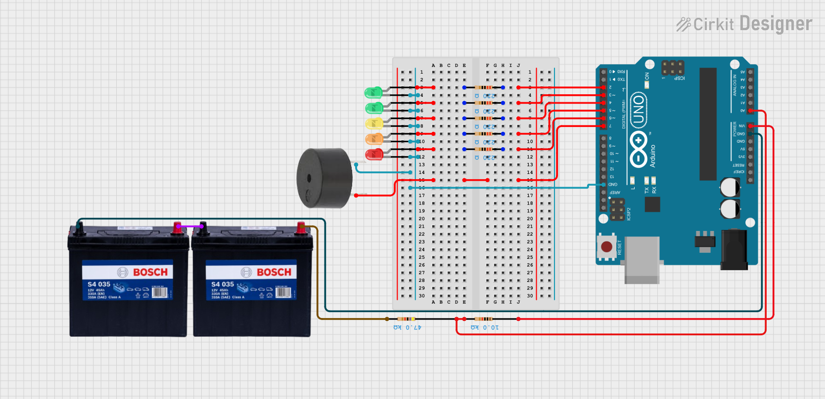
Circuit Documentation
Summary
This circuit is designed to monitor the voltage level of a 12V battery and visually indicate the charge level through a series of LEDs. It uses an Arduino UNO as the central microcontroller to read the battery voltage and control the LEDs and a buzzer. The LEDs represent different charge levels, and the buzzer is used as an audible warning when the battery charge is critically low. The circuit includes a voltage divider to step down the battery voltage to a level that can be read by the Arduino's analog input.
Component List
- Arduino UNO: A microcontroller board based on the ATmega328P. It has 14 digital input/output pins, 6 analog inputs, a USB connection, a power jack, an ICSP header, and a reset button.
- LEDs: Light Emitting Diodes of various colors (green, yellow, orange, red) used to indicate the battery charge level.
- Resistors: Various resistors are used in the circuit. 220 Ohm resistors are used to limit the current through the LEDs, and higher-value resistors (47k Ohms and 10k Ohms) are used to create a voltage divider for battery voltage measurement.
- Buzzer: An audible alert device that is activated when the battery charge is critically low.
- 12V 200Ah Battery: The power source for the circuit, which is being monitored for its voltage level.
Wiring Details
Arduino UNO
- Digital pins D2 to D6 are connected to the anodes of the LEDs through 220 Ohm resistors.
- Digital pin D7 is connected to the positive pin of the buzzer.
- Analog pin A0 is connected to a voltage divider network for battery voltage measurement.
- The GND pin is connected to the common ground of the circuit.
LEDs
- Each LED has its anode connected to a digital pin on the Arduino through a 220 Ohm resistor.
- The cathodes of all LEDs are connected to the common ground.
Resistors
- 220 Ohm resistors are connected in series with each LED to limit the current.
- A 47k Ohm resistor and a 10k Ohm resistor are used to form a voltage divider for the battery voltage measurement.
Buzzer
- The positive pin is connected to digital pin D7 on the Arduino.
- The negative pin is connected to the common ground.
12V 200Ah Battery
- The positive terminal is connected to the voltage divider network.
- The negative terminal is connected to the common ground of the circuit.
Documented Code
const int ledPins[] = {2, 3, 4, 5, 6}; // Array of LED pins
const int buzzerPin = 7; // Buzzer pin
const int batteryPin = A0; // Battery voltage measurement pin

void setup() {
  for (int i = 0; i < 5; i++) {
    pinMode(ledPins[i], OUTPUT); // Set LED pins as outputs
  }
  pinMode(buzzerPin, OUTPUT); // Set buzzer pin as output
  Serial.begin(9600); // Start serial communication
}

void loop() {
  int batteryLevel = analogRead(batteryPin); // Read battery voltage
  float voltage = batteryLevel * (5.0 / 1023.0) * (24.0 / 5.0); // Convert to actual voltage
  int percentage = (voltage / 24.0) * 100; // Calculate battery percentage

  // Print battery voltage and percentage to serial monitor
  Serial.print("Battery Voltage: ");
  Serial.print(voltage);
  Serial.print("V, Percentage: ");
  Serial.print(percentage);
  Serial.println("%");

  // Turn on LEDs based on battery percentage
  for (int i = 0; i < 5; i++) {
    if (percentage >= (i + 1) * 20) {
      digitalWrite(ledPins[i], HIGH);
    } else {
      digitalWrite(ledPins[i], LOW);
    }
  }

  // Activate buzzer if battery percentage is 30% or less
  if (percentage <= 30) {
    for (int i = 0; i < 3; i++) {
      digitalWrite(buzzerPin, HIGH);
      delay(500);
      digitalWrite(buzzerPin, LOW);
      delay(500);
    }
  }

  delay(1000); // Update every second
}
This code is designed to run on the Arduino UNO. It initializes the pins connected to the LEDs and the buzzer, reads the battery voltage through a voltage divider, calculates the battery percentage, and then updates the LEDs and buzzer accordingly. The serial monitor outputs the battery voltage and percentage for monitoring purposes.