Arduino UNO-Based Smart Home Automation System with I2C LCD and RTC
Circuit Documentation
Summary
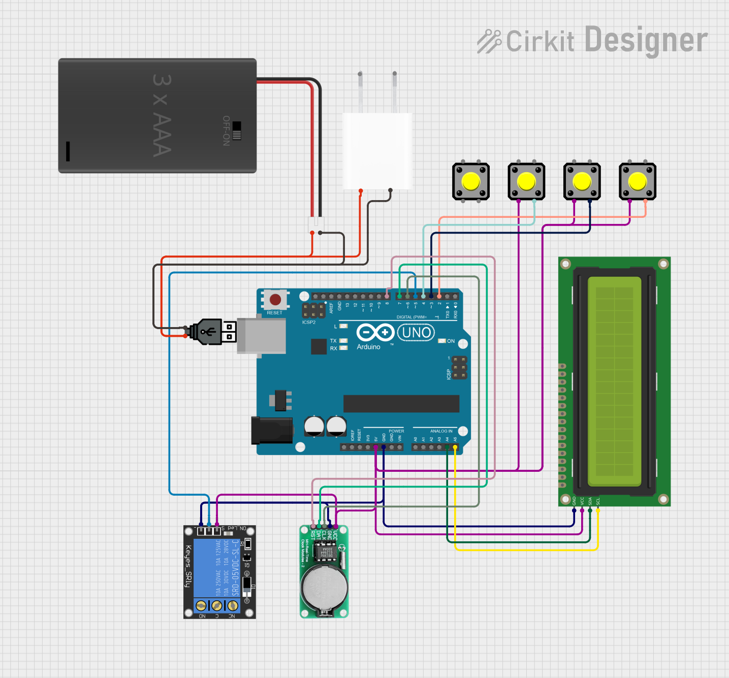
This circuit involves an Arduino UNO microcontroller interfacing with a 16x2 I2C LCD, a DS1302 RTC module, a 1-Channel Relay, and multiple pushbuttons. The circuit is powered by a 3xAAA Battery Pack with Switch and JST, USB power, or a 5V Adapter. The Arduino UNO controls the relay and reads inputs from the pushbuttons, while the LCD displays information and the RTC module keeps track of time.
Component List
Arduino UNO
- Description: A microcontroller board based on the ATmega328P.
- Pins: UNUSED, IOREF, Reset, 3.3V, 5V, GND, Vin, A0, A1, A2, A3, A4, A5, SCL, SDA, AREF, D13, D12, D11, D10, D9, D8, D7, D6, D5, D4, D3, D2, D1, D0
16x2 I2C LCD
- Description: A 16x2 character LCD display with I2C interface.
- Pins: GND, VCC, SDA, SCL
1-Channel Relay (5V 10A)
- Description: A relay module that can control high voltage devices.
- Pins: NC, signal, C, power, NO, ground
DS1302 RTC
- Description: A real-time clock module for keeping track of time.
- Pins: VCC, GND, CLK, DATA, RST
Pushbutton
- Description: A simple pushbutton switch.
- Pins: Pin 2, Pin 1, Pin 3, Pin 4
3xAAA Battery Pack with Switch and JST
- Description: A battery pack that holds three AAA batteries and includes a switch.
- Pins: POS, NEG
USB power
- Description: A USB power source.
- Pins: +, -
5V Adapter
- Description: A 5V power adapter.
- Pins: AC In 1, AC In 2, 5V, GND
Wiring Details
Arduino UNO
5V connected to:
- DS1302 RTC (VCC)
- 16x2 I2C LCD (VCC)
- Pushbutton (Pin 2)
- 1-Channel Relay (signal)
- Pushbutton (Pin 2)
- Pushbutton (Pin 2)
GND connected to:
- DS1302 RTC (GND)
- 16x2 I2C LCD (GND)
- 1-Channel Relay (ground)
A4 connected to:
- 16x2 I2C LCD (SDA)
A5 connected to:
- 16x2 I2C LCD (SCL)
D8 connected to:
- DS1302 RTC (RST)
D7 connected to:
- DS1302 RTC (DATA)
D6 connected to:
- DS1302 RTC (CLK)
D5 connected to:
- 1-Channel Relay (power)
D4 connected to:
- Pushbutton (Pin 3)
D3 connected to:
- Pushbutton (Pin 3)
D2 connected to:
- Pushbutton (Pin 3)
3xAAA Battery Pack with Switch and JST
POS connected to:
- USB power (+)
- 5V Adapter (5V)
NEG connected to:
- USB power (-)
- 5V Adapter (GND)
Documented Code
Arduino UNO Code (sketch.ino)
void setup() {
  // put your setup code here, to run once:

}

void loop() {
  // put your main code here, to run repeatedly:

}
Additional Documentation (documentation.txt)
This documentation provides a comprehensive overview of the circuit, including a summary, detailed component list, wiring details, and the code used in the Arduino UNO.