Arduino UNO R4 WiFi Controlled RGB LED with HC-SR04 Ultrasonic Sensor
Circuit Documentation
Summary
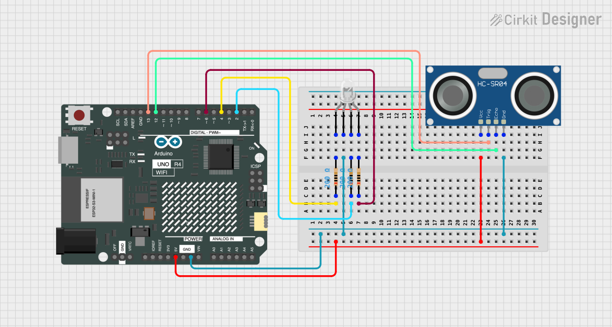
The circuit in question is designed to interface an Arduino UNO R4 WiFi with an HC-SR04 Ultrasonic Sensor and a common cathode RGB LED. The Arduino serves as the central processing unit, controlling the ultrasonic sensor for distance measurement and driving the RGB LED to display various colors. The circuit includes current-limiting resistors for each LED anode to protect the LED from excessive current.
Component List
Arduino UNO R4 WiFi
- Description: A microcontroller board based on the ATmega328, with integrated WiFi capabilities.
- Purpose: Acts as the central controller for the circuit, interfacing with the ultrasonic sensor and controlling the RGB LED.
HC-SR04 Ultrasonic Sensor
- Description: An ultrasonic distance sensor capable of measuring distances by emitting ultrasonic waves and measuring the time taken for the echo to return.
- Purpose: Used to measure distances, interfaced with the Arduino for data processing.
LED: Four Pin (Common Cathode)
- Description: An RGB LED with a common cathode and separate anodes for red, green, and blue LEDs.
- Purpose: Displays various colors under the control of the Arduino.
Resistor (200 Ohms)
- Description: A resistor with a resistance of 200 Ohms.
- Purpose: Limits the current flowing through the RGB LED to prevent damage.
Wiring Details
Arduino UNO R4 WiFi
- Digital Pin 4 (D4): Connected to a 200 Ohm resistor, which is then connected to the red anode of the RGB LED.
- Ground (GND): Common ground shared with the HC-SR04 Ultrasonic Sensor and the common cathode of the RGB LED.
- Digital Pin 2 (D2): Connected to a 200 Ohm resistor, which is then connected to the green anode of the RGB LED.
- Digital Pin 6 (D6): Connected to a 200 Ohm resistor, which is then connected to the blue anode of the RGB LED.
- 5V: Supplies power to the VCC pin of the HC-SR04 Ultrasonic Sensor.
- Digital Pin 13 (D13): Connected to the TRIG pin of the HC-SR04 Ultrasonic Sensor.
- Digital Pin 12 (D12): Connected to the ECHO pin of the HC-SR04 Ultrasonic Sensor.
HC-SR04 Ultrasonic Sensor
- VCC: Powered by the 5V output from the Arduino.
- TRIG: Trigger pin connected to Digital Pin 13 (D13) on the Arduino.
- ECHO: Echo pin connected to Digital Pin 12 (D12) on the Arduino.
- GND: Ground connection shared with the Arduino and the common cathode of the RGB LED.
LED: Four Pin (Common Cathode)
- Red Anode: Connected to a 200 Ohm resistor, which is then connected to Digital Pin 4 (D4) on the Arduino.
- Common Cathode: Connected to the ground (GND) shared with the Arduino and the HC-SR04 Ultrasonic Sensor.
- Green Anode: Connected to a 200 Ohm resistor, which is then connected to Digital Pin 2 (D2) on the Arduino.
- Blue Anode: Connected to a 200 Ohm resistor, which is then connected to Digital Pin 6 (D6) on the Arduino.
Resistor (200 Ohms)
- Resistor for Red Anode: One end connected to Digital Pin 4 (D4) on the Arduino, the other end to the red anode of the RGB LED.
- Resistor for Green Anode: One end connected to Digital Pin 2 (D2) on the Arduino, the other end to the green anode of the RGB LED.
- Resistor for Blue Anode: One end connected to Digital Pin 6 (D6) on the Arduino, the other end to the blue anode of the RGB LED.
Documented Code
void setup() {
  // put your setup code here, to run once:

}

void loop() {
  // put your main code here, to run repeatedly:

}
The provided code is a template with the standard setup() and loop() functions for an Arduino sketch. The setup() function is intended to contain initialization code that runs once when the microcontroller is powered on or reset. The loop() function contains the main logic of the sketch, which runs repeatedly as long as the microcontroller is powered.
Further implementation details would be required to control the HC-SR04 Ultrasonic Sensor and the RGB LED based on the desired functionality. This would involve writing code to send a pulse to the HC-SR04's TRIG pin, listen for the echo on the ECHO pin, calculate the distance, and then use this information to control the color and brightness of the RGB LED through the appropriate digital pins on the Arduino.