
ESP8266 NodeMCU-Based Smart Environmental Monitoring and Control System
View and Edit Project In Cirkit Designer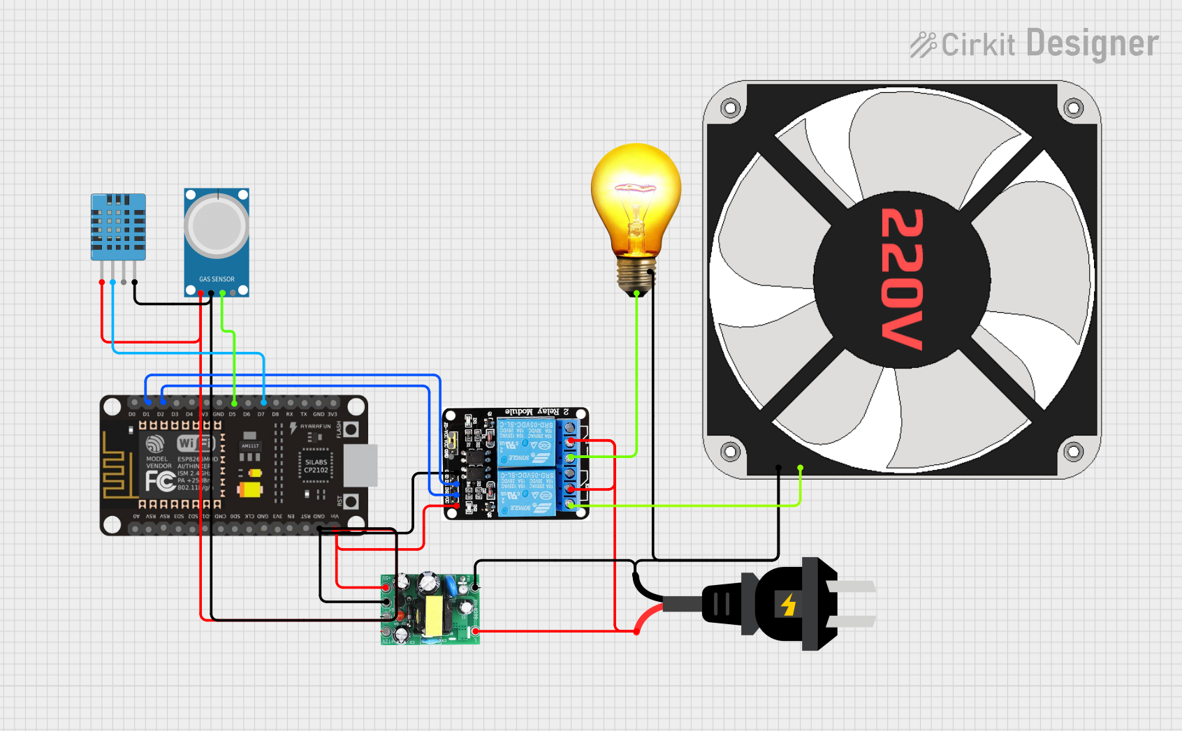
Circuit Documentation
Summary
The circuit in question is designed to interface an ESP8266 NodeMCU microcontroller with a variety of sensors and actuators for environmental monitoring and control. The circuit includes a DHT11 humidity and temperature sensor, an MQ-4 gas sensor, a 5V 2-Relay module, an AC bulb, and a 220V fan. Power is supplied by an AC source, which is converted to DC for the low-voltage components. The ESP8266 NodeMCU controls the relay module based on sensor inputs, which in turn controls the AC bulb and fan.
Component List
ESP8266 NodeMCU
- Microcontroller with WiFi capability.
- Pins: D0, D1, D2, D3, D4, 3V3, GND, D5, D6, D7, D8, RX, TX, A0, RSV, SD3, SD2, SD1, CMD, SD0, CLK, EN, RST, VIN
AC Source
- Provides the main power supply for the circuit.
- Pins: +, -
AC to DC Converter (actodc)
- Converts AC power to 5V and 12V DC.
- Pins: 12v, -, 5v, live, neutral
DHT11 Humidity and Temperature Sensor
- Measures ambient humidity and temperature.
- Pins: VDD, DATA, NULL, GND
5V 2-Relay Module (JD-VCC)
- Allows the microcontroller to control high-power devices.
- Pins: JD-VCC, VCC, GND, IN1, IN2, NO, COM, NC
AC Bulb
- An AC-powered light bulb.
- Pins: P, N
MQ-4 Gas Sensor
- Detects methane and natural gas in the air.
- Pins: A0, D0, GND, VCC
220V Fan
- An AC-powered fan.
- Pins: N, L
Wiring Details
ESP8266 NodeMCU
- GND connected to common ground.
- D1 controls Relay IN1.
- D2 controls Relay IN2.
- VIN connected to 5V power from the AC to DC converter.
- D5 connected to MQ-4 D0.
- D7 connected to DHT11 DATA.
AC Source
-
- connected to actodc live.
-
- connected to common ground.
AC to DC Converter (actodc)
- 12v not used in this circuit.
-
- connected to common ground.
- 5v supplies power to NodeMCU VIN, DHT11 VDD, MQ-4 VCC, and Relay VCC.
- live connected to AC source +.
- neutral connected to common ground.
DHT11 Humidity and Temperature Sensor
- VDD connected to 5V power from the AC to DC converter.
- DATA connected to NodeMCU D7.
- GND connected to common ground.
5V 2-Relay Module (JD-VCC)
- JD-VCC connected to 5V power from the AC to DC converter.
- VCC connected to 5V power from the AC to DC converter.
- GND connected to common ground.
- IN1 controlled by NodeMCU D1.
- IN2 controlled by NodeMCU D2.
- NO of Relay 1 connected to AC Bulb P and 220V Fan L.
- COM connected to AC source +.
AC Bulb
- P connected to NO of Relay 1.
- N connected to common ground.
MQ-4 Gas Sensor
- A0 not used in this circuit.
- D0 connected to NodeMCU D5.
- GND connected to common ground.
- VCC connected to 5V power from the AC to DC converter.
220V Fan
- L connected to NO of Relay 1.
- N connected to common ground.
Documented Code
No code was provided for the microcontroller. The expected behavior, based on the wiring, would be for the NodeMCU to read data from the DHT11 and MQ-4 sensors and control the relay module accordingly. The relay module would then switch the AC bulb and fan on or off based on the sensor readings and programmed logic within the NodeMCU. Without the code, the specific conditions and logic for controlling the relays cannot be documented.