Cirkit Designer
Your all-in-one circuit design IDE
Home /
Project Documentation
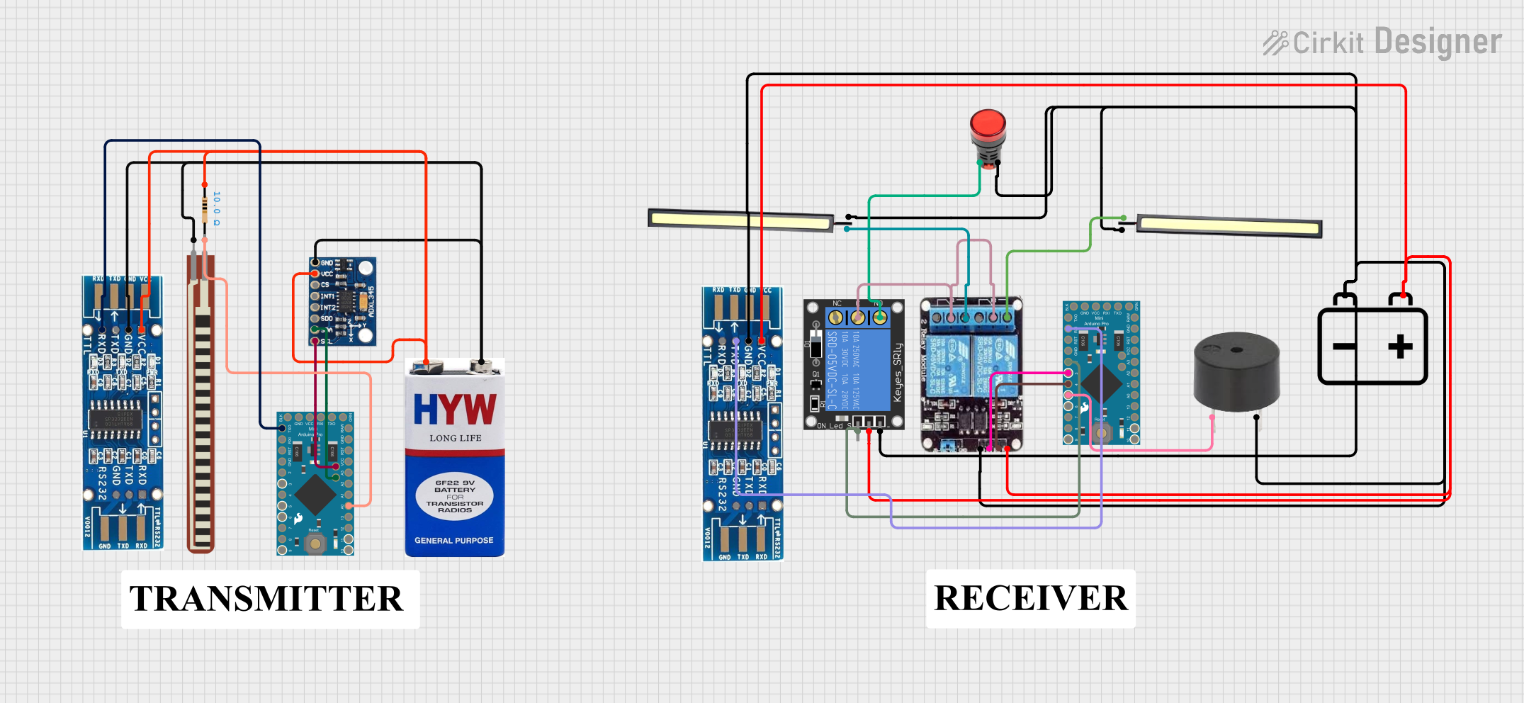
Arduino Pro Mini-Based Smart Home Automation with ADXL345 and RS232 Communication
Circuit Documentation
Summary
This document provides a detailed overview of a circuit that includes various components such as Arduino Pro Mini microcontrollers, sensors, relays, LEDs, and other electronic components. The circuit is designed to interface with multiple devices and perform specific tasks as programmed in the microcontrollers.
Component List
Arduino Pro Mini v13
- Pins: DTR, D0/TX, D1/RX, VCC, GND, A4, A5, RAW, RESET, A3, A2, A1, A0, D13/SCK, D12/MISO, D11 PWM/MOSI, D10 PWM/SS, D9 PWM, D8, D7, D6 PWM, D5 PWM, D4, D3 PWM, D2
- Description: A compact microcontroller board based on the ATmega328P.
9V Battery
- Pins: +, -
- Description: A standard 9V battery used to power the circuit.
Resistor
- Pins: pin1, pin2
- Description: A 10 Ohm resistor used for current limiting.
- Properties: Resistance: 10 Ohms
2.2 inch Basic Flex Resistor
- Pins: Pin 2, pin 1
- Description: A flexible resistor used for sensing bending or flexing.
RS232
- Pins: GND, TXD, RXD, VCC
- Description: A serial communication interface.
1-Channel Relay (5V 10A)
- Pins: NC, signal, C, power, NO, ground
- Description: A relay module used to control high voltage devices.
LED 12V
- Pins: POSITIF, NEGATIF
- Description: A 12V LED used for indication.
Buzzer
- Pins: PIN, GND
- Description: A buzzer used for sound indication.
ADXL345
- Pins: GND, VCC, CS, INT1, INT2, SDO, SDA, SCL
- Description: A 3-axis accelerometer used for motion sensing.
12V Battery
- Pins: -, +
- Description: A 12V battery used to power the circuit.
2-Channel Relay
- Pins: NC, COM, NO, VCC, IN2, IN1, GND
- Description: A relay module used to control multiple high voltage devices.
Lamp Red
- Pins: +, -
- Description: A red lamp used for indication.
Wiring Details
Arduino Pro Mini v13
- A4 connected to ADXL345 SDA
- A5 connected to ADXL345 SCL
- A0 connected to Resistor pin2
- D0/TX connected to RS232 RXD
- D1/RX connected to RS232 TXD
- D4 connected to 2-Channel Relay IN2
- D3 PWM connected to 2-Channel Relay IN1
- D2 connected to 1-Channel Relay signal
- D5 PWM connected to Buzzer PIN
9V Battery
- + connected to Resistor pin1, RS232 VCC, ADXL345 VCC
- - connected to RS232 GND, ADXL345 GND, 2.2 inch Basic Flex Resistor pin 1
Resistor
- pin1 connected to 9V Battery +
- pin2 connected to Arduino Pro Mini v13 A0
2.2 inch Basic Flex Resistor
- pin 1 connected to 9V Battery -
- Pin 2 not connected
RS232
- GND connected to 9V Battery -
- TXD connected to Arduino Pro Mini v13 D1/RX
- RXD connected to Arduino Pro Mini v13 D0/TX
- VCC connected to 9V Battery +
1-Channel Relay (5V 10A)
- ground connected to RS232 GND, Buzzer GND, 2-Channel Relay GND, LED 12V NEGATIF, 12V Battery -, Lamp Red -
- power connected to RS232 VCC, 2-Channel Relay VCC, 12V Battery +
- C connected to 2-Channel Relay COM
- signal connected to Arduino Pro Mini v13 D2
- NO connected to Lamp Red +
LED 12V
- POSITIF connected to 2-Channel Relay NO
- NEGATIF connected to 1-Channel Relay ground
Buzzer
- PIN connected to Arduino Pro Mini v13 D5 PWM
- GND connected to 1-Channel Relay ground
ADXL345
- GND connected to 9V Battery -
- VCC connected to 9V Battery +
- SDA connected to Arduino Pro Mini v13 A4
- SCL connected to Arduino Pro Mini v13 A5
12V Battery
- - connected to 1-Channel Relay ground
- + connected to 1-Channel Relay power
2-Channel Relay
- GND connected to 1-Channel Relay ground
- VCC connected to 1-Channel Relay power
- COM connected to 1-Channel Relay C
- NO connected to LED 12V POSITIF
- IN2 connected to Arduino Pro Mini v13 D4
- IN1 connected to Arduino Pro Mini v13 D3 PWM
Lamp Red
- + connected to 1-Channel Relay NO
- - connected to 1-Channel Relay ground
Documented Code
Arduino Pro Mini v13 (Instance 1)
void setup() {
  // put your setup code here, to run once:

}

void loop() {
  // put your main code here, to run repeatedly:

}
Arduino Pro Mini v13 (Instance 2)
void setup() {
  // put your setup code here, to run once:

}

void loop() {
  // put your main code here, to run repeatedly:

}
This documentation provides a comprehensive overview of the circuit, including the components used, their connections, and the code running on the microcontrollers.