
ESP32-Based Wi-Fi Controlled Robotic System with Multiple Sensors and Motor Drivers
View and Edit Project In Cirkit Designer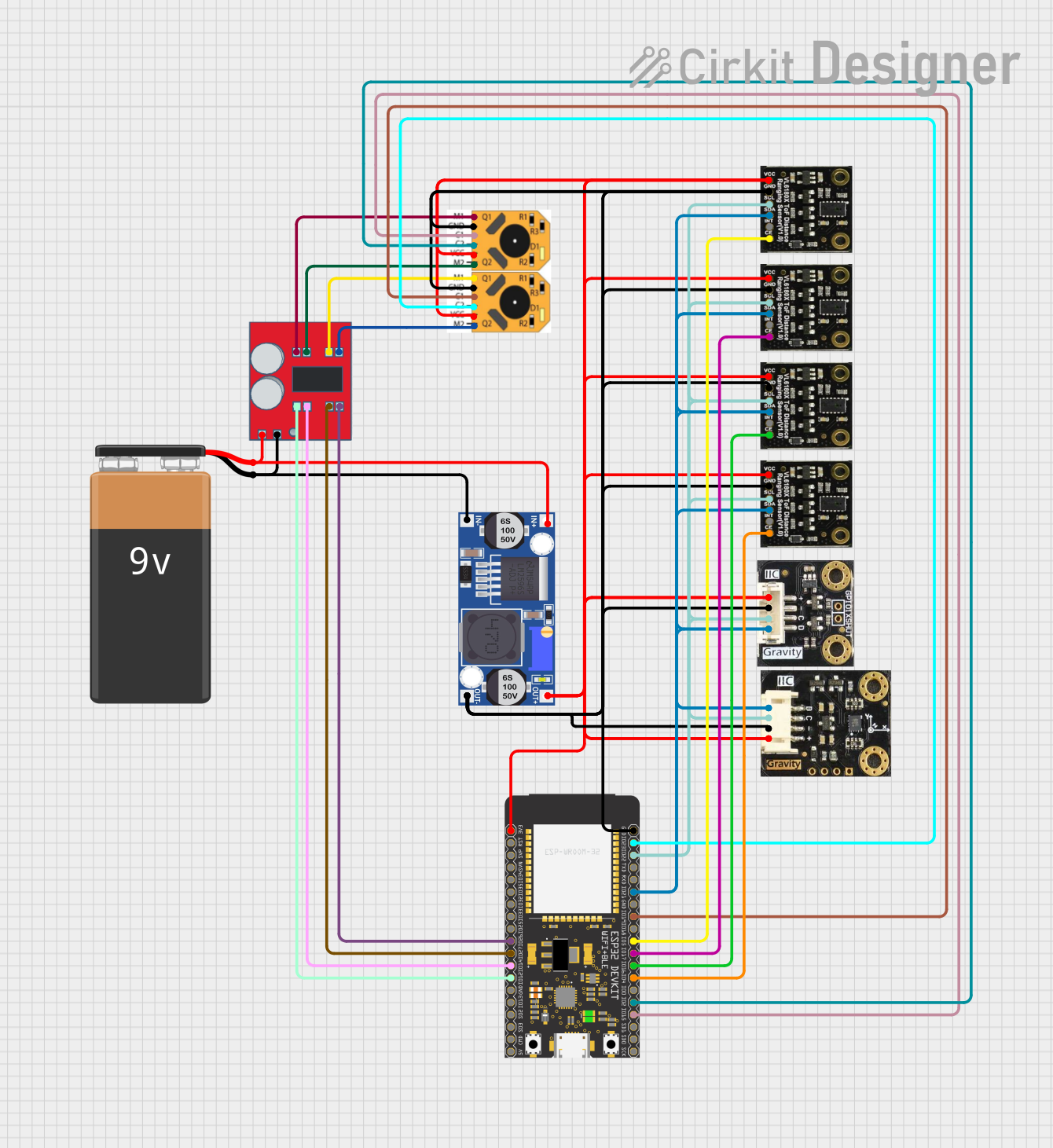
Circuit Documentation
Summary
This document provides a detailed overview of a circuit design that includes various sensors, a motor driver, a microcontroller, and power management components. The circuit is designed to interface multiple sensors and motors with an ESP32 microcontroller, powered by a 9V battery through a buck converter.
Component List
SEN0245
- Description: Sensor module
- Pins: VCC, GND, SCL, SDA, INT, CE
SEN0427
- Description: Sensor module
- Pins: VCC, GND, SCL, SDA, INT, CE
I2C BMI160
- Description: I2C-based sensor
- Pins: DATA, CLK, GND, VCC
n20 motor with encoder
- Description: Motor with encoder
- Pins: M1, GND, C1, C2, Vcc, M2
9V Battery
- Description: Power source
- Pins: -, +
MX1508 DC Motor Driver
- Description: Motor driver
- Pins: OUT 4, OUT 3, OUT 2, OUT1, IN 1, IN 2, IN 3, IN 4, Negative (-), Positive (+)
Buck converter
- Description: Voltage regulator
- Pins: IN+, IN-, OUT+, OUT-
ESP32 Wroom
- Description: Microcontroller
- Pins: 2 (3V3), 3 (Reset), 4 (GPIO36), 5 (GPIO39), 6 (GPIO34), 7 (GPIO35), 8 (GPIO32), 9 (GPIO33), 10 (GPIO25), 11 (GPIO26), 12 (GPIO27), 13 (GPIO14), 14 (GPIO12), GND, 16 (GPIO13), 17 (GPIO9), 18 (GPIO10), 19 (GPIO11), 5V, 37 (GPIO23), 36 (GPIO22/SCL), 35 (GPIO1/TXD0), 34 (GPIO3/RXD0), 33 (GPIO21/SDA), 31 (GPIO19), 30 (GPIO18), 29 (GPIO5), 28 (GPIO17), 27 (GPIO16), 26 (GPIO4), 25 (GPIO0), 24 (GPIO2), 23 (GPIO15), 22 (GPIO8), 21 (GPIO7), 20 (GPIO6)
Wiring Details
SEN0245
- VCC connected to Buck converter OUT+
- GND connected to Buck converter OUT-
- SCL connected to ESP32 Wroom GPIO22/SCL
- SDA connected to ESP32 Wroom GPIO21/SDA
- CE connected to ESP32 Wroom GPIO5
SEN0427
- VCC connected to Buck converter OUT+
- GND connected to Buck converter OUT-
- SCL connected to ESP32 Wroom GPIO22/SCL
- SDA connected to ESP32 Wroom GPIO21/SDA
- CE connected to ESP32 Wroom GPIO4
I2C BMI160
- VCC connected to Buck converter OUT+
- GND connected to Buck converter OUT-
- CLK connected to ESP32 Wroom GPIO22/SCL
- DATA connected to ESP32 Wroom GPIO21/SDA
n20 motor with encoder
- Vcc connected to Buck converter OUT+
- GND connected to Buck converter OUT-
- M1 connected to MX1508 DC Motor Driver OUT1
- M2 connected to MX1508 DC Motor Driver OUT2
- C1 connected to ESP32 Wroom GPIO19
- C2 connected to ESP32 Wroom GPIO23
9V Battery
- + connected to MX1508 DC Motor Driver Positive (+) and Buck converter IN+
- - connected to MX1508 DC Motor Driver Negative (-) and Buck converter IN-
MX1508 DC Motor Driver
- OUT 1 connected to n20 motor with encoder M1
- OUT 2 connected to n20 motor with encoder M2
- OUT 3 connected to n20 motor with encoder M1
- OUT 4 connected to n20 motor with encoder M2
- IN 1 connected to ESP32 Wroom GPIO12
- IN 2 connected to ESP32 Wroom GPIO14
- IN 3 connected to ESP32 Wroom GPIO27
- IN 4 connected to ESP32 Wroom GPIO26
- Positive (+) connected to 9V Battery +
- Negative (-) connected to 9V Battery -
Buck converter
- IN+ connected to 9V Battery +
- IN- connected to 9V Battery -
- OUT+ connected to VCC pins of all sensors and ESP32 Wroom 3V3
- OUT- connected to GND pins of all sensors and ESP32 Wroom GND
ESP32 Wroom
- 3V3 connected to Buck converter OUT+
- GND connected to Buck converter OUT-
- GPIO22/SCL connected to SCL pins of I2C BMI160, SEN0427, and SEN0245
- GPIO21/SDA connected to SDA pins of I2C BMI160, SEN0427, and SEN0245
- GPIO5 connected to SEN0245 CE
- GPIO4 connected to SEN0427 CE
- GPIO17 connected to SEN0245 CE
- GPIO16 connected to SEN0427 CE
- GPIO19 connected to n20 motor with encoder C1
- GPIO23 connected to n20 motor with encoder C2
- GPIO15 connected to n20 motor with encoder C1
- GPIO2 connected to n20 motor with encoder C2
- GPIO12 connected to MX1508 DC Motor Driver IN 1
- GPIO14 connected to MX1508 DC Motor Driver IN 2
- GPIO27 connected to MX1508 DC Motor Driver IN 3
- GPIO26 connected to MX1508 DC Motor Driver IN 4
Code
No code provided for this circuit.
This document provides a comprehensive overview of the circuit, including a summary, component list, wiring details, and code documentation. Each component is described, and its connections are detailed to ensure proper assembly and functionality.