Arduino-Controlled Fire Detection and GSM Notification System
Circuit Documentation
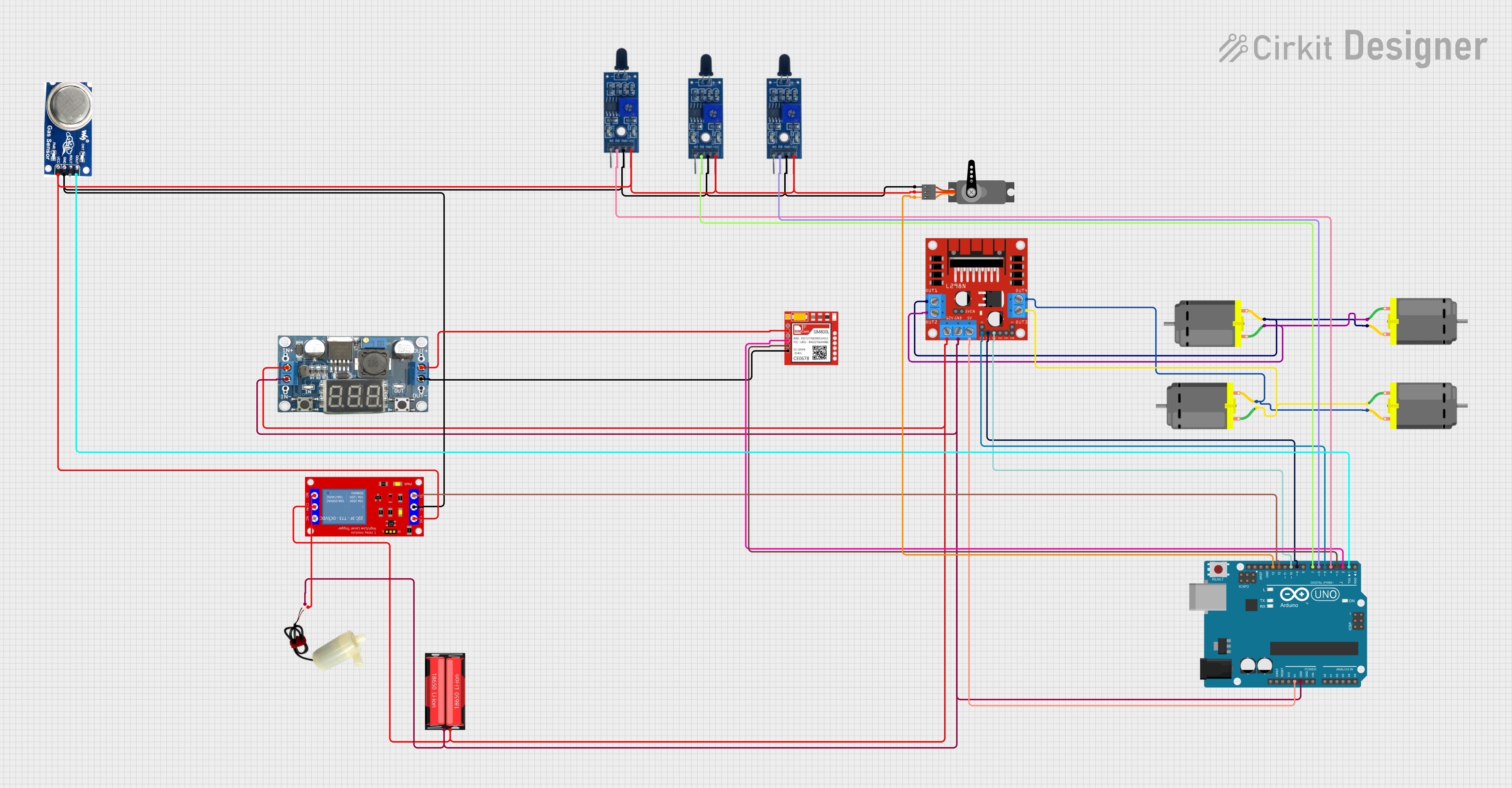
Summary
This circuit is designed to control multiple DC motors using an L298N DC motor driver, interfaced with an Arduino UNO microcontroller. The circuit includes power management components such as an 18650 Li-Ion battery and an LM296 DC-DC converter, as well as sensors like flame sensors and a smoke sensor for safety monitoring. A servo motor is included for additional actuation, and a Sim800l module is present for potential communication capabilities. A 5V mini water pump is controlled via a 1 Channel 5V Relay Module, which is also interfaced with the Arduino UNO.
Component List
- L298N DC Motor Driver: A module used for controlling up to two DC motors with direction and speed control.
- 18650 Li-Ion Battery: A rechargeable battery providing power to the circuit.
- Arduino UNO: A microcontroller board based on the ATmega328P, used for controlling the various components of the circuit.
- DC Motors: Four motors controlled by the L298N driver for movement or actuation purposes.
- Flame Sensors: Sensors that detect the presence of a flame or fire, used for safety monitoring.
- Smoke Sensor: A sensor that detects the presence of smoke, also used for safety monitoring.
- 5V Mini Water Pump: A pump controlled by the relay module for moving water or other liquids.
- Sim800l: A GSM/GPRS module that can be used for cellular communication.
- LM296 DC-DC Converter: A power converter that steps down voltage levels for certain components.
- 1 Channel 5V Relay Module: A relay that allows the Arduino to control higher power devices like the water pump.
- Servo: A motor capable of precise position control, used for angular movement.
Wiring Details
L298N DC Motor Driver
- OUT1, OUT2: Connected to two DC motors.
- OUT3, OUT4: Connected to two other DC motors.
- 12V: Connected to the positive terminal of the 18650 Li-Ion battery through a relay module.
- GND: Common ground with Arduino UNO, 5V mini water pump, LM296 DC-DC, and 18650 Li-Ion battery.
- 5V: Connected to the 5V output of the Arduino UNO.
- ENA, ENB: Control signals from Arduino UNO (D5).
- IN1, IN2, IN3, IN4: Control signals from Arduino UNO (D9, D10).
18650 Li-Ion Battery
- Positive: Connected to the 12V input of the L298N and the input of the relay module.
- Negative: Common ground.
Arduino UNO
- GND: Common ground.
- 5V: Provides power to the L298N.
- Digital Pins (D2-D13): Control signals for the L298N, relay module, flame sensors, smoke sensor, Sim800l, and servo.
DC Motors
- Pin 1, Pin 2: Connected to the respective outputs of the L298N.
Flame Sensors
- VCC: Connected to the 5V rail.
- GND: Common ground.
- D0: Digital output connected to Arduino UNO digital pins (D4, D6, D7).
Smoke Sensor
- VCC: Connected to the 5V rail.
- GND: Common ground.
- DO: Digital output connected to Arduino UNO (D1).
5V Mini Water Pump
- Positive Pin: Connected to the normally open (N.O.) contact of the relay module.
- Negative Pin: Common ground.
Sim800l
- VCC: Connected to the output of the LM296 DC-DC converter.
- GND: Common ground.
- RXD, TXD: Communication lines connected to Arduino UNO (D2, D3).
LM296 DC-DC Converter
- Vin: Connected to the positive terminal of the 18650 Li-Ion battery.
- GNDin: Common ground.
- Vout: Provides power to the Sim800l.
- GNDout: Common ground.
1 Channel 5V Relay Module
- VCC+: Connected to the 5V rail.
- VCC- (GND): Common ground.
- IN: Control signal from Arduino UNO (D12).
- N.O.: Connected to the positive pin of the 5V mini water pump.
- COM: Connected to the positive terminal of the 18650 Li-Ion battery.
Servo
- GND: Common ground.
- VCC: Connected to the 5V rail.
- PWM: Control signal from Arduino UNO (D13).
Documented Code
Arduino UNO Code
// Define L298N motor control pins
int enA = 5;  // Enable Pin A
int in1 = 9;  // Input Pin 1
int in2 = 10; // Input Pin 2

void setup() {
  // Set the motor control pins as outputs
  pinMode(enA, OUTPUT);
  pinMode(in1, OUTPUT);
  pinMode(in2, OUTPUT);
}

void loop() {
  // Motor Forward
  digitalWrite(in1, HIGH);
  digitalWrite(in2, LOW);
  analogWrite(enA, 200); // Set motor speed (0-255)

  delay(2000); // Run forward for 2 seconds

  // Motor Stop
  digitalWrite(in1, LOW);
  digitalWrite(in2, LOW);
  analogWrite(enA, 0);

  delay(1000); // Stop for 1 second

  // Motor Reverse
  digitalWrite(in1, LOW);
  digitalWrite(in2, HIGH);
  analogWrite(enA, 200); // Set motor speed (0-255)

  delay(2000); // Run reverse for 2 seconds

  // Motor Stop
  digitalWrite(in1, LOW);
  digitalWrite(in2, LOW);
  analogWrite(enA, 0);

  delay(1000); // Stop for 1 second
}
L298N DC Motor Driver Code
void setup() {
  // put your setup code here, to run once:

}

void loop() {
  // put your main code here, to run repeatedly:

}
Note: The code for the L298N DC motor driver is not complete and does not contain any functional code. It is likely that the control code is intended to be placed on the Arduino UNO, which sends the control signals to the L298N.