
ESP32-Based Environmental Monitoring and Weight Detection System with Camera and Display
View and Edit Project In Cirkit Designer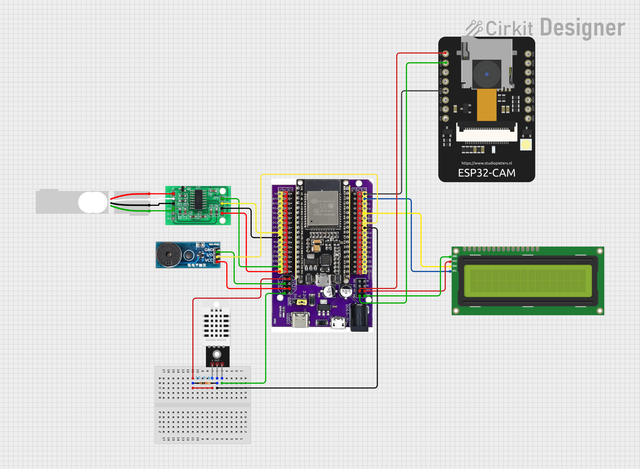
Circuit Documentation
Summary
This circuit integrates various components to perform multiple functions. It includes an ESP32 on a baseboard, which serves as the central processing unit, an ESP32 CAM for image capture, an I2C LCD 16x2 screen for display, a DHT22 sensor for measuring temperature and humidity, a 10kΩ resistor, an HX711 bridge sensor interface for load cell data acquisition, a load cell for weight measurement, and a buzzer module for audio feedback. The ESP32 on the baseboard is the primary microcontroller and is responsible for interfacing with all other components.
Component List
ESP32 on Baseboard
- Microcontroller with Wi-Fi and Bluetooth capabilities.
- Multiple GPIO pins for interfacing with peripherals.
ESP32 CAM
- A small-sized camera module.
- Can be used for image capture and processing.
I2C LCD 16x2 Screen
- A 16x2 character LCD display.
- Uses I2C communication protocol.
DHT22
- A sensor for measuring ambient temperature and humidity.
Resistor (10kΩ)
- A passive component used to limit current or divide voltages.
HX711 - Bridge Sensor Interface
- A precision 24-bit analog-to-digital converter (ADC) designed for weigh scales and industrial control applications to interface directly with a bridge sensor.
Load Cell - Red/white/black/green
- A transducer that converts force into an electrical signal.
Buzzer Module
- An audio signaling device.
Wiring Details
ESP32 on Baseboard
- GPIO5 connected to DHT22 (Data Out) through a 10kΩ resistor.
- GPIO23 connected to ESP32 CAM (GPIO15).
- GPIO22 connected to I2C LCD Screen (SCL).
- GPIO21 connected to I2C LCD Screen (SDA).
- GPIO18 connected to Buzzer Module (I/O).
- GPIO26 connected to HX711 (DATA Out).
- GPIO27 connected to HX711 (SCK - CLOCK In).
- 5V connected to DHT22 (+) and I2C LCD Screen (VCC 5V).
- 3V connected to Buzzer Module (Vcc).
- GND connected to DHT22 (-), I2C LCD Screen (GND), Buzzer Module (GND), and HX711 (GND - GROUND).
ESP32 CAM
- 5V connected to ESP32 on Baseboard (VCC).
- GND connected to ESP32 on Baseboard (GND).
I2C LCD 16x2 Screen
- SCL connected to ESP32 on Baseboard (GPIO22).
- SDA connected to ESP32 on Baseboard (GPIO21).
- VCC (5V) connected to ESP32 on Baseboard (VCC).
- GND connected to ESP32 on Baseboard (GND).
DHT22
- '+' connected to ESP32 on Baseboard (5V).
- 'Out' connected to ESP32 on Baseboard (GPIO5) through a 10kΩ resistor.
- '-' connected to ESP32 on Baseboard (GND).
Resistor (10kΩ)
- Pin1 connected to DHT22 (Out).
- Pin2 connected to ESP32 on Baseboard (GPIO5).
HX711 - Bridge Sensor Interface
- DATA (OUT) connected to ESP32 on Baseboard (GPIO26).
- SCK - CLOCK (IN) connected to ESP32 on Baseboard (GPIO27).
- GND - GROUND connected to ESP32 on Baseboard (GND).
- 3.3/3.5V Supply connected to ESP32 on Baseboard (5V).
- E+ connected to Load Cell (E+).
- E- connected to Load Cell (A-).
- A- connected to Load Cell (E-).
- A+ connected to Load Cell (A+).
Load Cell - Red/white/black/green
- E+ connected to HX711 (E+).
- A- connected to HX711 (E-).
- E- connected to HX711 (A-).
- A+ connected to HX711 (A+).
Buzzer Module
- I/O connected to ESP32 on Baseboard (GPIO18).
- Vcc connected to ESP32 on Baseboard (3V).
- GND connected to ESP32 on Baseboard (GND).
Documented Code
No code has been provided for the microcontrollers in the circuit. The documentation of the code would typically include descriptions of the functions, initialization of peripherals, main loop, and any interrupt service routines. Since no code is available, this section cannot be completed. If code becomes available, it should be documented here with explanations of how it interacts with the hardware components listed above.