Cirkit Designer
Your all-in-one circuit design IDE
Home /
Project Documentation
Arduino UNO Based User Input Interface with LCD Feedback and Keypad Control

Circuit Documentation
Summary
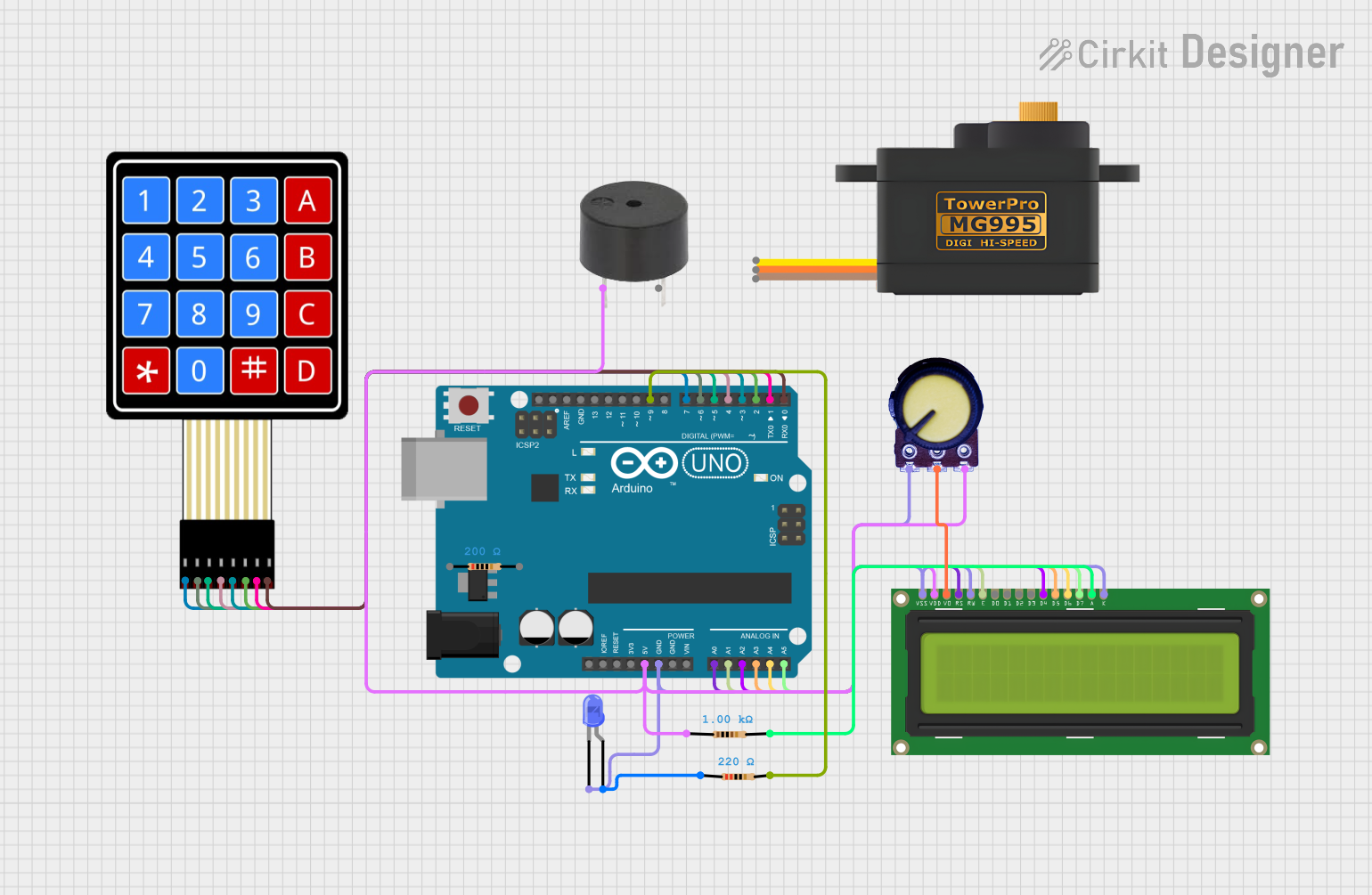
This document provides a detailed overview of a circuit that includes an Arduino UNO microcontroller, a 4x4 membrane matrix keypad, a 16x2 LCD display, various resistors, a blue LED, a buzzer, a potentiometer, and a servomotor (MG995). The circuit is designed to interface with the keypad and display user input on the LCD, while also providing visual (LED) and audible (buzzer) feedback. The potentiometer is used to adjust the contrast of the LCD display, and the servomotor is controlled by the Arduino UNO.
Component List
Microcontroller
- Arduino UNO: A microcontroller board based on the ATmega328P. It has digital input/output pins, analog inputs, a USB connection for programming, and power management features.
Input Devices
- 4X4 Membrane Matrix Keypad: A 16-button keypad that provides a simple user interface for inputting commands or data.
Output Devices
- LCD Display 16x2: A liquid crystal display capable of displaying 16 characters per line across 2 lines, used for showing information to the user.
- LED: Two Pin (blue): A blue light-emitting diode used as a visual indicator.
- buzzer: An electronic buzzer for audible alerts or feedback.
- Servomotor MG995: A high-torque servomotor for precise control of mechanical movement.
Passive Components
- Resistors: Three resistors with different resistance values (200 Ohms, 1000 Ohms, and 220 Ohms) used for current limiting and voltage division.
- Potentiometer: A variable resistor used to adjust the contrast of the LCD display.
Wiring Details
Arduino UNO
- 5V: Powers the LCD display, potentiometer, and buzzer.
- GND: Common ground for the LCD display, potentiometer, LED, and buzzer.
- A0 - A5: Connected to the RS, E, DB4, DB5, DB6, and DB7 pins of the LCD display for data and control signals.
- D0 - D9: Connected to the keypad and LED through resistors for input scanning and LED control.
4X4 Membrane Matrix Keypad
- R1 - R4: Connected to digital pins D7 - D4 of the Arduino UNO for row scanning.
- C1 - C4: Connected to digital pins D3 - D0 of the Arduino UNO for column scanning.
LCD Display 16x2
- VDD: Connected to the 5V supply from the Arduino UNO.
- LEDA: Connected to the 5V supply through a 1000 Ohm resistor for backlight control.
- DB7 - DB4: Connected to analog pins A5 - A2 of the Arduino UNO for data transfer.
- RS, E: Connected to analog pins A0 and A1 of the Arduino UNO for control signals.
- VO: Connected to the output of the potentiometer for contrast adjustment.
- VSS, RW, LEDK: Connected to GND.
LED: Two Pin (blue)
- anode: Connected to digital pin D9 of the Arduino UNO through a 220 Ohm resistor.
- cathode: Connected to GND.
Buzzer
- PIN: Connected to the 5V supply from the Arduino UNO.
- GND: Connected to GND.
Potentiometer
- VCC: Connected to the 5V supply from the Arduino UNO.
- Output: Connected to the VO pin of the LCD display for contrast control.
- GND: Connected to GND.
Servomotor MG995
- SIG: Signal pin to be connected to a PWM-capable pin on the Arduino UNO (not detailed in the net list).
- VCC: Power supply (not detailed in the net list).
- GND: Ground connection (not detailed in the net list).
Documented Code
Arduino UNO Code (sketch.ino)
void setup() {
  // put your setup code here, to run once:

}

void loop() {
  // put your main code here, to run repeatedly:

}
Note: The provided code is a template and does not include specific functionality. It should be populated with the setup and loop functions to initialize the components and define the main behavior of the circuit.