Cirkit Designer
Your all-in-one circuit design IDE
Home /
Project Documentation
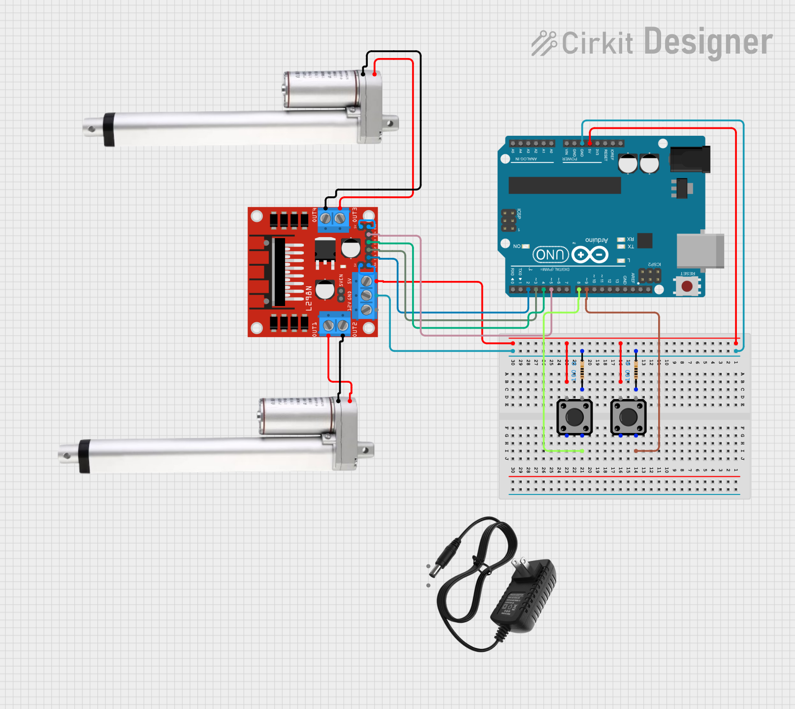
Arduino UNO and L298N Motor Driver Controlled Linear Actuators with Tactile Switches
Circuit Documentation
Summary
This circuit controls two linear actuators using an L298N motor driver and an Arduino UNO. The actuators extend 4 inches when a button is pressed and retract to zero when another button is pressed. The actuators move at a rate of 0.31 inches per second.
Component List
Actuator Motor
- Description: Motor used to drive the linear actuators.
- Pins: 12 V, Ground
Tactile Switch Buttons - 12mm Square
- Description: Buttons used to control the extension and retraction of the actuators.
- Pins: 3, 1, 4, 2
L298N DC Motor Driver
- Description: Motor driver used to control the actuator motors.
- Pins: OUT1, OUT2, 12V, GND, 5V, OUT3, OUT4, 5V-ENA-JMP-I, 5V-ENA-JMP-O, +5V-J1, +5V-J2, ENA, IN1, IN2, IN3, IN4, ENB
Arduino UNO
- Description: Microcontroller used to control the motor driver and read button inputs.
- Pins: UNUSED, IOREF, Reset, 3.3V, 5V, GND, Vin, A0, A1, A2, A3, A4, A5, SCL, SDA, AREF, D13, D12, D11, D10, D9, D8, D7, D6, D5, D4, D3, D2, D1, D0
12V Power Supply
- Description: Power supply for the circuit.
- Pins: +, -
Resistor
- Description: Resistor used in the circuit.
- Pins: pin1, pin2
- Properties: Resistance: 100 Ohms
Wiring Details
Actuator Motor
- Pin 12 V connected to L298N DC Motor Driver OUT1
- Pin Ground connected to L298N DC Motor Driver OUT2
Actuator Motor
- Pin 12 V connected to L298N DC Motor Driver OUT3
- Pin Ground connected to L298N DC Motor Driver OUT4
Tactile Switch Buttons - 12mm Square
- Pin 4 connected to Arduino UNO D9
Tactile Switch Buttons - 12mm Square
- Pin 4 connected to Arduino UNO D8
L298N DC Motor Driver
- Pin 5V connected to Arduino UNO 5V
- Pin GND connected to Arduino UNO GND and Resistor pin2
- Pin OUT1 connected to Actuator Motor 12 V
- Pin OUT2 connected to Actuator Motor Ground
- Pin OUT3 connected to Actuator Motor 12 V
- Pin OUT4 connected to Actuator Motor Ground
- Pin ENA connected to L298N DC Motor Driver +5V-J1
- Pin ENB connected to L298N DC Motor Driver +5V-J2
- Pin IN1 connected to Arduino UNO D2
- Pin IN2 connected to Arduino UNO D3
- Pin IN3 connected to Arduino UNO D4
- Pin IN4 connected to Arduino UNO D5
Arduino UNO
- Pin D9 connected to Tactile Switch Buttons - 12mm Square pin 4
- Pin D8 connected to Tactile Switch Buttons - 12mm Square pin 4
- Pin 5V connected to L298N DC Motor Driver 5V
- Pin GND connected to L298N DC Motor Driver GND and Resistor pin2
- Pin D2 connected to L298N DC Motor Driver IN1
- Pin D3 connected to L298N DC Motor Driver IN2
- Pin D4 connected to L298N DC Motor Driver IN3
- Pin D5 connected to L298N DC Motor Driver IN4
Resistor
- Pin pin2 connected to Arduino UNO GND and L298N DC Motor Driver GND
Code Documentation
/*
 * This Arduino sketch controls two linear actuators using an L298N motor driver.
 * The actuators extend 4 inches when a button is pressed and retract to zero
 * when another button is pressed. The actuators move at a rate of 0.31 inches
 * per second.
 */

const int buttonExtend1 = 8; // Button to extend actuator 1
const int buttonRetract1 = 9; // Button to retract actuator 1
const int buttonExtend2 = 10; // Button to extend actuator 2
const int buttonRetract2 = 11; // Button to retract actuator 2

const int in1 = 2; // L298N IN1
const int in2 = 3; // L298N IN2
const int in3 = 4; // L298N IN3
const int in4 = 5; // L298N IN4

const int actuatorTime = 12903; // Time to move 4 inches at 0.31 inches/sec

void setup() {
  pinMode(buttonExtend1, INPUT);
  pinMode(buttonRetract1, INPUT);
  pinMode(buttonExtend2, INPUT);
  pinMode(buttonRetract2, INPUT);
  pinMode(in1, OUTPUT);
  pinMode(in2, OUTPUT);
  pinMode(in3, OUTPUT);
  pinMode(in4, OUTPUT);
}

void loop() {
  if (digitalRead(buttonExtend1) == HIGH) {
    extendActuator(in1, in2);
  } else if (digitalRead(buttonRetract1) == HIGH) {
    retractActuator(in1, in2);
  }

  if (digitalRead(buttonExtend2) == HIGH) {
    extendActuator(in3, in4);
  } else if (digitalRead(buttonRetract2) == HIGH) {
    retractActuator(in3, in4);
  }
}

void extendActuator(int pin1, int pin2) {
  digitalWrite(pin1, HIGH);
  digitalWrite(pin2, LOW);
  delay(actuatorTime);
  digitalWrite(pin1, LOW);
}

void retractActuator(int pin1, int pin2) {
  digitalWrite(pin1, LOW);
  digitalWrite(pin2, HIGH);
  delay(actuatorTime);
  digitalWrite(pin2, LOW);
}
This code initializes the pins for the buttons and motor driver, and in the main loop, it checks the state of the buttons to control the extension and retraction of the actuators. The extendActuator and retractActuator functions handle the actual movement of the actuators by setting the appropriate pins on the motor driver.