
ESP32 and RFM95 LoRa Transmitter with Inductor-Based Antenna
View and Edit Project In Cirkit Designer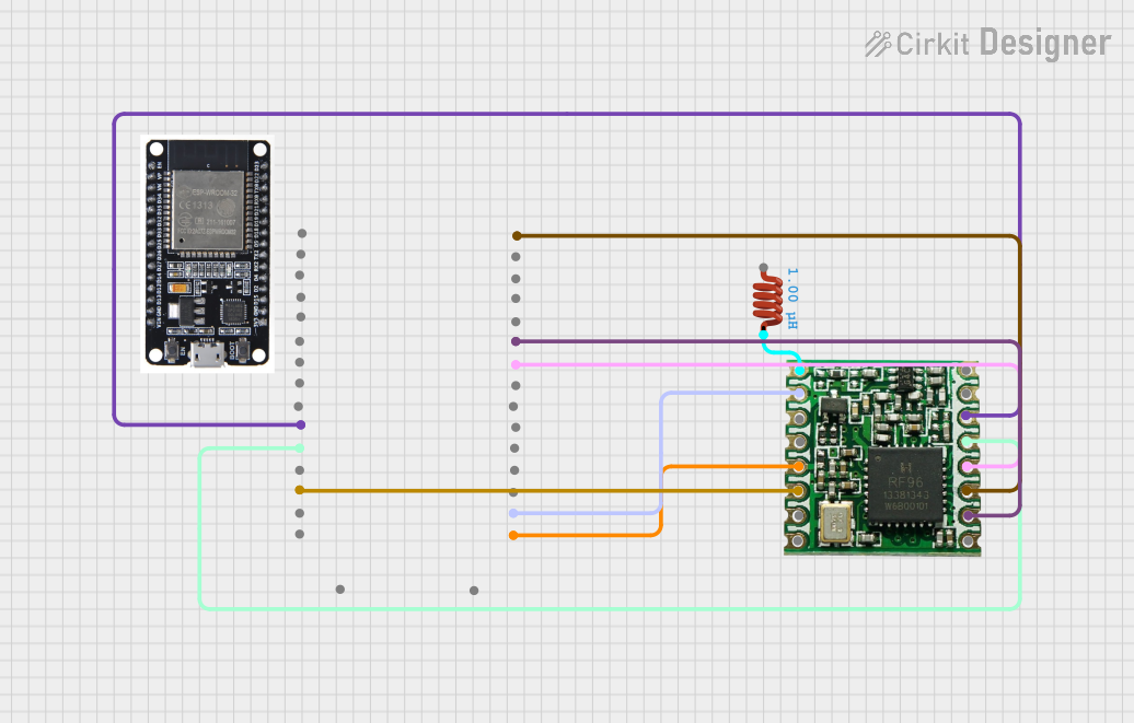
Circuit Documentation
Summary
This document provides a detailed overview of a circuit that integrates an ESP32 microcontroller with an RFM95 LoRa module and an inductor. The ESP32 is programmed to initialize the LoRa module and send a simple message periodically.
Component List
ESP32
- Description: A powerful microcontroller with integrated Wi-Fi and Bluetooth capabilities.
- Pins: EN, VP, VN, D34, D35, D32, D33, D25, D26, D27, D14, D12, D13, GND, VIN, 3V3, D15, D2, D4, RX2, TX2, D5, D18, D19, D21, RX0, TX0, D22, D23, BOOT
RFM95
- Description: A LoRa transceiver module used for long-range communication.
- Pins: DIO2, DIO1, DIO0, 3.3V, DIO4, DIO3, GND, ANT, MISO, MOSI, SCK, NSS, RESET, DIO5
Inductor
- Description: A passive electronic component that stores energy in a magnetic field.
- Pins: pin 0, pin 1
- Properties:
- Inductance: 1 µH
Wiring Details
ESP32
- D13 is connected to RFM95 DIO0
- 3V3 is connected to RFM95 3.3V
- GND is connected to RFM95 GND
- D19 is connected to RFM95 MISO
- D23 is connected to RFM95 MOSI
- D18 is connected to RFM95 SCK
- D14 is connected to RFM95 NSS
- D27 is connected to RFM95 RESET
RFM95
- DIO0 is connected to ESP32 D13
- 3.3V is connected to ESP32 3V3
- GND is connected to ESP32 GND
- MISO is connected to ESP32 D19
- MOSI is connected to ESP32 D23
- SCK is connected to ESP32 D18
- NSS is connected to ESP32 D14
- RESET is connected to ESP32 D27
- ANT is connected to Inductor pin 1
Inductor
- pin 1 is connected to RFM95 ANT
Code Documentation
/*
 * LoRa Transmitter
 * This Arduino sketch configures an ESP32 to communicate with an RFM95 LoRa
 * module. The ESP32 will initialize the LoRa module and send a simple message.
 */

#include <SPI.h>
#include <LoRa.h>

// Pin definitions
#define LORA_SS 14
#define LORA_RST 27
#define LORA_DIO0 13

void setup() {
  // Initialize serial communication
  Serial.begin(9600);
  while (!Serial);
  Serial.println("LoRa Transmitter");

  // Setup LoRa transceiver module
  LoRa.setPins(LORA_SS, LORA_RST, LORA_DIO0);

  if (!LoRa.begin(915E6)) { // Initialize LoRa at 915 MHz
    Serial.println("Starting LoRa failed!");
    while (1);
  }
  Serial.println("LoRa Initializing OK!");
}

void loop() {
  Serial.println("Sending packet...");
  // Send packet
  LoRa.beginPacket();
  LoRa.print("Hello, world!");
  LoRa.endPacket();

  delay(5000); // Wait for 5 seconds before sending next packet
}
This code initializes the LoRa module connected to the ESP32 and sends a "Hello, world!" message every 5 seconds. The pin definitions in the code match the wiring details provided above.