Cirkit Designer
Your all-in-one circuit design IDE
Home /
Project Documentation
ESP32 CAM Wi-Fi Controlled Live Video Streamer with FTDI Programmer
Circuit Documentation
Summary
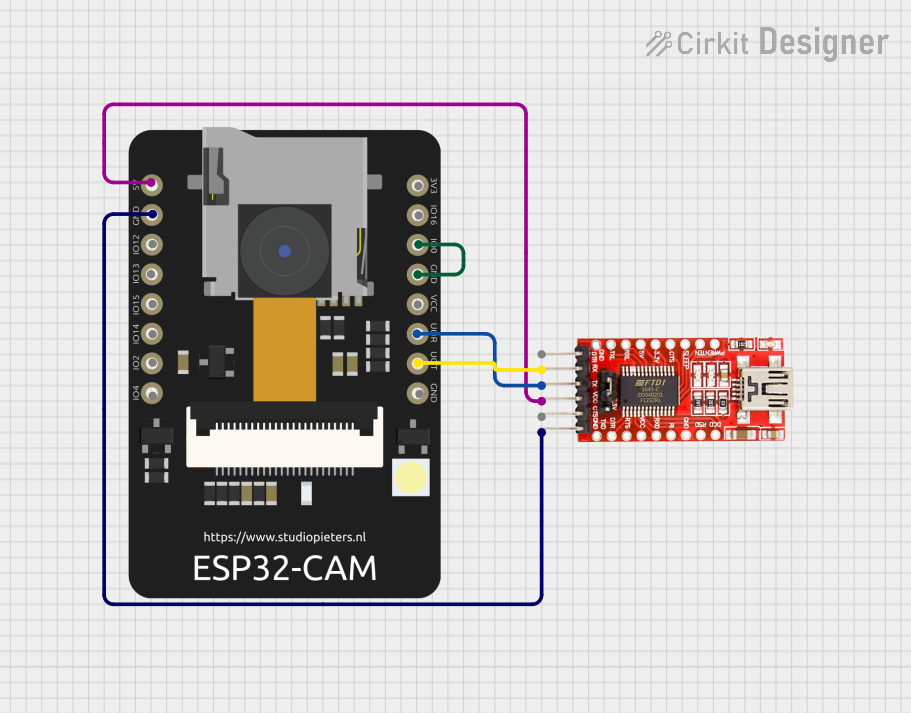
This document provides a detailed overview of a circuit involving an ESP32 CAM module and an FTDI Programmer. The ESP32 CAM is used for capturing images and streaming them over WiFi, while the FTDI Programmer is used for programming the ESP32 CAM. The document includes a list of components, wiring details, and the embedded code used in the circuit.
Component List
ESP32 CAM
- Description: The ESP32 CAM is a small-sized camera module that integrates an ESP32-S chip, a camera, and a microSD card slot. It is capable of capturing images and streaming video over WiFi.
- Pins:
- 5V
- GND
- GPIO12
- GPIO13
- GPIO15
- GPIO14
- GPIO2
- GPIO4
- 3.3V
- GPIO16
- GPIO0
- 3.3V / 5V / P_OUT
- GPIO3 / RX
- GPIO1 / TX
FTDI Programmer
- Description: The FTDI Programmer is used to program microcontrollers via USB. It provides a serial interface for communication and programming.
- Pins:
- DTR
- RX
- TX
- VCC
- CTS
- GND
Wiring Details
ESP32 CAM
- 5V: Connected to FTDI Programmer VCC
- GND: Connected to FTDI Programmer GND
- GPIO0: Connected to ESP32 CAM GND
- GPIO3 / RX: Connected to FTDI Programmer TX
- GPIO1 / TX: Connected to FTDI Programmer RX
FTDI Programmer
- VCC: Connected to ESP32 CAM 5V
- GND: Connected to ESP32 CAM GND
- TX: Connected to ESP32 CAM GPIO3 / RX
- RX: Connected to ESP32 CAM GPIO1 / TX
Code Documentation
ESP32 CAM Code
#include "src/OV2640.h"
#include <WiFi.h>
#include <WebServer.h>
#include <WiFiClient.h>

// Select camera model
//#define CAMERA_MODEL_WROVER_KIT
#define CAMERA_MODEL_ESP_EYE
//#define CAMERA_MODEL_M5STACK_PSRAM
//#define CAMERA_MODEL_M5STACK_WIDE
//#define CAMERA_MODEL_AI_THINKER

#include "camera_pins.h"

#define SSID1 "ssid"
#define PWD1 "password"

OV2640 cam;

WebServer server(80);

const char HEADER[] = "HTTP/1.1 200 OK\r\n" \
                      "Access-Control-Allow-Origin: *\r\n" \
                      "Content-Type: multipart/x-mixed-replace; boundary=123456789000000000000987654321\r\n";
const char BOUNDARY[] = "\r\n--123456789000000000000987654321\r\n";
const char CTNTTYPE[] = "Content-Type: image/jpeg\r\nContent-Length: ";
const int hdrLen = strlen(HEADER);
const int bdrLen = strlen(BOUNDARY);
const int cntLen = strlen(CTNTTYPE);

void handle_jpg_stream(void)
{
  char buf[32];
  int s;

  WiFiClient client = server.client();

  client.write(HEADER, hdrLen);
  client.write(BOUNDARY, bdrLen);

  while (true)
  {
    if (!client.connected()) break;
    cam.run();
    s = cam.getSize();
    client.write(CTNTTYPE, cntLen);
    sprintf( buf, "%d\r\n\r\n", s );
    client.write(buf, strlen(buf));
    client.write((char *)cam.getfb(), s);
    client.write(BOUNDARY, bdrLen);
  }
}

const char JHEADER[] = "HTTP/1.1 200 OK\r\n" \
                       "Content-disposition: inline; filename=capture.jpg\r\n" \
                       "Content-type: image/jpeg\r\n\r\n";
const int jhdLen = strlen(JHEADER);

void handle_jpg(void)
{
  WiFiClient client = server.client();

  cam.run();
  if (!client.connected()) return;

  client.write(JHEADER, jhdLen);
  client.write((char *)cam.getfb(), cam.getSize());
}

void handleNotFound()
{
  String message = "Server is running!\n\n";
  message += "URI: ";
  message += server.uri();
  message += "\nMethod: ";
  message += (server.method() == HTTP_GET) ? "GET" : "POST";
  message += "\nArguments: ";
  message += server.args();
  message += "\n";
  server.send(200, "text / plain", message);
}

void setup()
{
  Serial.begin(115200);
  //while (!Serial);            //wait for serial connection.

  camera_config_t config;
  config.ledc_channel = LEDC_CHANNEL_0;
  config.ledc_timer = LEDC_TIMER_0;
  config.pin_d0 = Y2_GPIO_NUM;
  config.pin_d1 = Y3_GPIO_NUM;
  config.pin_d2 = Y4_GPIO_NUM;
  config.pin_d3 = Y5_GPIO_NUM;
  config.pin_d4 = Y6_GPIO_NUM;
  config.pin_d5 = Y7_GPIO_NUM;
  config.pin_d6 = Y8_GPIO_NUM;
  config.pin_d7 = Y9_GPIO_NUM;
  config.pin_xclk = XCLK_GPIO_NUM;
  config.pin_pclk = PCLK_GPIO_NUM;
  config.pin_vsync = VSYNC_GPIO_NUM;
  config.pin_href = HREF_GPIO_NUM;
  config.pin_sscb_sda = SIOD_GPIO_NUM;
  config.pin_sscb_scl = SIOC_GPIO_NUM;
  config.pin_pwdn = PWDN_GPIO_NUM;
  config.pin_reset = RESET_GPIO_NUM;
  config.xclk_freq_hz = 20000000;
  config.pixel_format = PIXFORMAT_JPEG;

  // Frame parameters
  //  config.frame_size = FRAMESIZE_UXGA;
  config.frame_size = FRAMESIZE_QVGA;
  config.jpeg_quality = 12;
  config.fb_count = 2;

#if defined(CAMERA_MODEL_ESP_EYE)
  pinMode(13, INPUT_PULLUP);
  pinMode(14, INPUT_PULLUP);
#endif

  cam.init(config);

  IPAddress ip;

  WiFi.mode(WIFI_STA);
  WiFi.begin(SSID1, PWD1);
  while (WiFi.status() != WL_CONNECTED)
  {
    delay(500);
    Serial.print(F("."));
  }
  ip = WiFi.localIP();
  Serial.println(F("WiFi connected"));
  Serial.println("");
  Serial.println(ip);
  Serial.print("Stream Link: http://");
  Serial.print(ip);
  Serial.println("/mjpeg/1");
  server.on("/mjpeg/1", HTTP_GET, handle_jpg_stream);
  server.on("/jpg", HTTP_GET, handle_jpg);
  server.onNotFound(handleNotFound);
  server.begin();
}

void loop()
{
  server.handleClient();
}
This code initializes the ESP32 CAM module, connects it to a WiFi network, and sets up a web server to stream video and capture images. The camera configuration is set for JPEG format with a frame size of QVGA. The web server handles different routes to stream video and capture images in JPEG format.