
Circuit Documentation
Summary
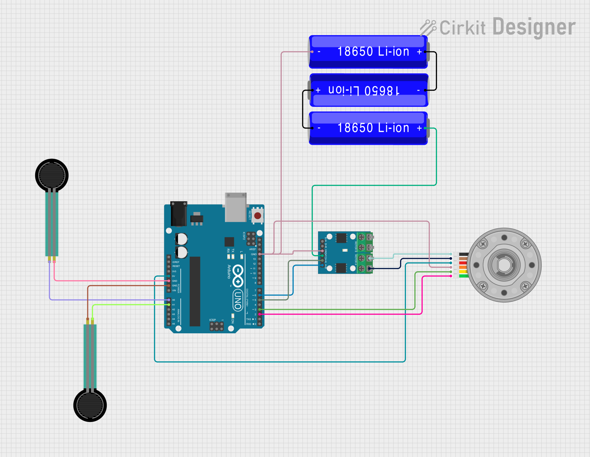
This circuit integrates an Arduino UNO microcontroller with a DC motor equipped with an encoder, an L9110 motor driver, two force sensing resistors (FSRs), and a power supply consisting of three 18650 Li-ion batteries. The Arduino UNO controls the motor via the L9110 driver and reads the encoder signals to determine the motor's position. The FSRs provide input to the Arduino, which can be used to trigger events or measure force applied to the sensors. The batteries provide power to the motor driver and the Arduino, with one battery also connected in series to another to increase the voltage.
Component List
Arduino UNO
- Microcontroller board based on the ATmega328P
- It has 14 digital input/output pins, 6 analog inputs, a 16 MHz quartz crystal, a USB connection, a power jack, an ICSP header, and a reset button.
DC Motor with Encoder
- A motor that provides rotational motion with the added feature of an encoder for position feedback.
- The encoder outputs are connected to the Arduino for position tracking.
L9110 Motor Driver
- An H-bridge motor driver that allows for direction and speed control of a motor.
- It interfaces with the Arduino to control the DC motor.
Force Sensing Resistor (FSR)
- A sensor that changes its resistance based on the force applied to its surface.
- Two FSRs are used in this circuit to provide force feedback to the Arduino.
18650 Li-ion Battery
- A rechargeable battery that provides power to the circuit.
- Three batteries are used, with two connected in series and one in parallel to provide the required voltage and current.
Wiring Details
Arduino UNO
5Vpin provides power to the DC Motor's VCC.GNDpins are common ground for the FSRs, DC Motor, and L9110.A0andA1pins are connected to the FSRs for analog input.D6andD5pins control the L9110 motor driver inputs.D3andD2pins read the encoder outputs from the DC Motor.
DC Motor with Encoder
VCCandGNDpins are powered by the Arduino's 5V and GND.Encoder AandEncoder Bpins are connected to the Arduino's D3 and D2 for position feedback.Motor +veandMotor -vepins are connected to the L9110 motor driver.
L9110 Motor Driver
MOTOR A-AandMOTOR A-Bcontrol the motor's terminals.A-IAandA-IBreceive control signals from the Arduino's D5 and D6.GNDandVCCare connected to the battery's negative and positive terminals, respectively.
Force Sensing Resistor (FSR)
- One pin is connected to the Arduino's analog input (A0 or A1).
- The other pin is connected to the Arduino's GND.
18650 Li-ion Battery
- One battery's positive terminal is connected to the L9110's VCC.
- The negative terminal is connected to the Arduino's GND and the L9110's GND.
- Two batteries are connected in series, and their combined output is connected in parallel with the third battery to provide power.
Documented Code
Arduino UNO Code (sketch.ino)
void setup() {
  // put your setup code here, to run once:

}

void loop() {
  // put your main code here, to run repeatedly:

}
Additional Notes
- The provided code is a template and does not contain any functional code for controlling the motor or reading the sensors. The user must implement the setup and loop functions to initialize the motor driver and read the encoder and force sensor values.
- The
documentation.txtfile is empty and can be used to add additional notes or documentation related to the code.