Cirkit Designer
Your all-in-one circuit design IDE
Home /
Project Documentation
ESP32-Controlled Sensor Interface with Rotary Encoders and Proximity Sensing

Circuit Documentation
Summary
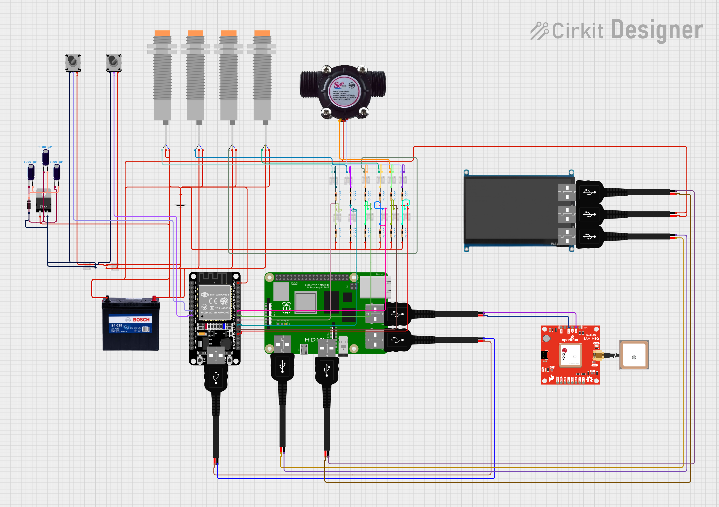
This document provides a detailed overview of a complex circuit that includes a variety of components such as microcontrollers, sensors, capacitors, resistors, connectors, and power sources. The circuit appears to be designed for interfacing with various sensors and input devices, processing signals, and providing power regulation. Notably, the circuit includes an ESP32 microcontroller and a Raspberry Pi 4B, which suggests that it is intended for applications requiring significant processing power and connectivity options.
Component List
Microcontrollers
- ESP32 (30 pin): A powerful microcontroller with Wi-Fi and Bluetooth capabilities, featuring a wide range of GPIO pins for interfacing with various peripherals.
- Raspberry Pi 4B: A compact single-board computer with a broad set of features including GPIO pins, USB ports, and video output, suitable for complex computing tasks.
Sensors
- LJ18A3-H-ZBX Inductive Proximity Sensor: A sensor used to detect the presence of metallic objects without direct contact.
- water flow sensor: A sensor used to measure the flow rate of water through a pipe or channel.
- SparkFun_Ublox SAM-M8Q: A GPS module for location tracking.
- Antenna GPS Embedded SMA: An antenna designed for receiving GPS signals.
Input Devices
- Rotary Encoder: An input device that provides rotational position feedback.
Display
- 7 inch WaveShare (H): A display module with HDMI, VGA, and touch capabilities.
Power Components
- 12V 200Ah Battery: A high-capacity battery providing a 12V power source.
- Voltage Regulator: A device that maintains a constant voltage level to the load.
- USB male 2 pin connection: A connector for USB power delivery.
Passive Components
- Electrolytic Capacitor: A capacitor used for filtering and power smoothing in the circuit.
- Diode: A component that allows current to flow in one direction only, often used for protection against reverse polarity.
- Resistor: A passive two-terminal electrical component that implements electrical resistance as a circuit element.
Connectors
- JST PH 2.0 connector: A common connector used for making detachable electrical connections.
- GND: A ground connection point.
Wiring Details
ESP32 (30 pin)
- EN: [Wiring details not provided]
- VP: [Wiring details not provided]
- VN: [Wiring details not provided]
- D34: [Wiring details not provided]
- D35: [Wiring details not provided]
- D32: [Wiring details not provided]
- D33: Connected to Rotary Encoder common pin
- D25: Connected to Rotary Encoder common pin
- D23: Connected to various sensors and components
- D14: [Wiring details not provided]
- D12: [Wiring details not provided]
- D13: [Wiring details not provided]
- GND: [Wiring details not provided]
- Vin: [Wiring details not provided]
- D19: [Wiring details not provided]
- D18: Connected to a resistor
- D5: Connected to a resistor
- TX0: [Wiring details not provided]
- RX0: [Wiring details not provided]
- TX2: Connected to a JST PH 2.0 connector
- RX2: Connected to a JST PH 2.0 connector
- D4: Connected to a JST PH 2.0 connector
- D2: Connected to a JST PH 2.0 connector
- D15: [Wiring details not provided]
- 3V3: [Wiring details not provided]
Raspberry Pi 4B
- [Wiring details not provided for Raspberry Pi 4B]
Electrolytic Capacitor
- -: Connected to the ground side of the Voltage Regulator
- +: Connected to the output side of the Voltage Regulator and the anode of the Diode
Diode
- cathode: Connected to the positive side of the Electrolytic Capacitors
- anode: Connected to the output side of the Voltage Regulator
Resistor
- pin1: Connected to various JST PH 2.0 connectors
- pin2: Connected to various components including the ESP32, Rotary Encoder, and sensors
JST PH 2.0 connector
- 1: Connected to various sensors and input devices
- 2: Connected to the ESP32 and other components
USB male 2 pin connection
- Negative -: Connected to various components including the SparkFun_Ublox SAM-M8Q and other USB connections
- Positive +: Connected to various components including the SparkFun_Ublox SAM-M8Q and other USB connections
12V 200Ah Battery
- GND: Connected to the ground network
- 12V: [Wiring details not provided]
LJ18A3-H-ZBX Inductive Proximity Sensor
- VO (BLU): Connected to the input side of the Voltage Regulator
- VI (BRN): Connected to the input side of the Voltage Regulator
- SIG (BLK): Connected to various JST PH 2.0 connectors
Voltage Regulator
- IN: Connected to the LJ18A3-H-ZBX Inductive Proximity Sensor
- GND: Connected to the ground side of the Electrolytic Capacitors
- OUT: Connected to the Rotary Encoder and the anode of the Diode
Rotary Encoder
- EncoderPinA (output pin A): Connected to the output side of the Voltage Regulator
- EncoderPinC (common): Connected to the ESP32 (D33 and D25)
- EncoderPinB (output pin B): Connected to resistors and various sensors
Documented Code
No code has been provided for the microcontrollers in the circuit. If code becomes available, it should be documented here with appropriate comments and explanations for each function and routine.