
ESP32-Based Security System with Fingerprint Access, Vibration Detection, and GPS Tracking
View and Edit Project In Cirkit Designer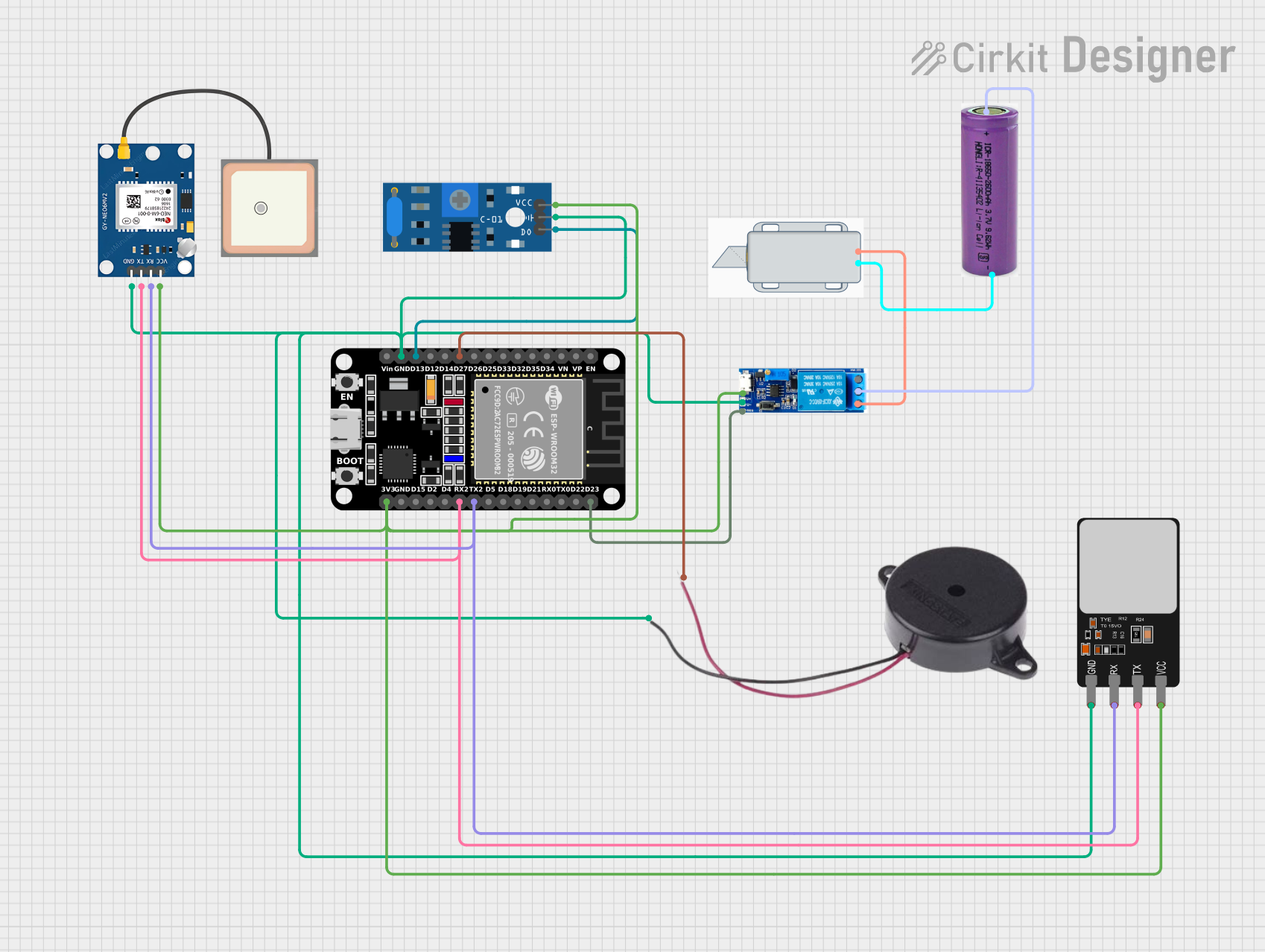
Circuit Documentation
Summary
The circuit in question appears to be designed for security or access control purposes, featuring a variety of components including a solenoid lock, a relay module, a vibration sensor, a fingerprint scanner, a buzzer, an ESP32 microcontroller, a GPS module, and a 3.3V battery. The ESP32 serves as the central processing unit, interfacing with the fingerprint scanner and GPS module via serial communication, driving a buzzer, and receiving input from a vibration sensor. The relay module is used to control the power to the solenoid lock, which is likely the actuating mechanism for a locking system. The 3.3V battery provides power to the circuit.
Component List
12V Solenoid Lock
- Description: An electromechanical lock that can be actuated by applying 12V across its terminals.
- Pins:
-(Ground),+(Positive)
Relay Module 5V-30V
- Description: An electrically operated switch that allows a low-power signal to control a higher power circuit.
- Pins:
common contact,normally open,normally closed,trigger,V-(Ground),V+(Positive)
SW-420 Vibration Sensor
- Description: A sensor that detects vibrations and outputs a digital signal.
- Pins:
vcc(Power),Ground,Digital output
Fingerprint Scanner
- Description: A biometric sensor that captures fingerprints for identification purposes.
- Pins:
VCC(Power),TX(Transmit),RX(Receive),GND(Ground)
Buzzer
- Description: An audio signaling device that can emit a tone when powered.
- Pins:
POSITIVE,NEGATIVE
ESP32 (30 pin)
- Description: A microcontroller with Wi-Fi and Bluetooth capabilities, suitable for a variety of applications.
- Pins:
EN,VP,VN,D34,D35,D32,D33,D25,D26,D27,D14,D12,D13,GND,Vin,D23,D22,TX0,RX0,D21,D19,D18,D5,TX2,RX2,D4,D2,D15,3V3
GPS NEO 6M
- Description: A GPS module capable of providing geolocation and time information.
- Pins:
VCC(Power),RX(Receive),TX(Transmit),GND(Ground)
3.3V Battery
- Description: A power source for the circuit.
- Pins:
+(Positive),-(Negative)
Wiring Details
12V Solenoid Lock
- Negative (-): Connected to the negative terminal of the 3.3V battery.
- Positive (+): Connected to the
normally openpin of the Relay Module.
Relay Module 5V-30V
- Common Contact: Connected to the positive terminal of the 3.3V battery.
- Normally Open: Connected to the
+pin of the 12V Solenoid Lock. - Normally Closed: Not connected.
- Trigger: Connected to the
D23pin of the ESP32. - V- (Ground): Shared ground with other components.
- V+ (Positive): Connected to the
3V3pin of the ESP32.
SW-420 Vibration Sensor
- VCC (Power): Connected to the
3V3pin of the ESP32. - Ground: Shared ground with other components.
- Digital Output: Connected to the
D13pin of the ESP32.
Fingerprint Scanner
- VCC (Power): Connected to the
3V3pin of the ESP32. - TX (Transmit): Connected to the
RX2pin of the ESP32. - RX (Receive): Connected to the
TX2pin of the ESP32. - GND (Ground): Shared ground with other components.
Buzzer
- POSITIVE: Connected to the
D27pin of the ESP32. - NEGATIVE: Shared ground with other components.
ESP32 (30 pin)
- D27: Connected to the
POSITIVEpin of the Buzzer. - D13: Connected to the
Digital Outputpin of the SW-420 Vibration Sensor. - GND: Shared ground with other components.
- D23: Connected to the
Triggerpin of the Relay Module. - TX2: Connected to the
RXpin of the Fingerprint Scanner. - RX2: Connected to the
TXpin of the Fingerprint Scanner. - 3V3: Power supply to the Fingerprint Scanner, SW-420 Vibration Sensor, Relay Module, and GPS NEO 6M.
GPS NEO 6M
- VCC (Power): Connected to the
3V3pin of the ESP32. - RX (Receive): Connected to the
TX2pin of the ESP32. - TX (Transmit): Connected to the
RX2pin of the ESP32. - GND (Ground): Shared ground with other components.
3.3V Battery
- Positive (+): Connected to the
Common Contactpin of the Relay Module. - Negative (-): Connected to the
-pin of the 12V Solenoid Lock.
Documented Code
There is no code provided for the microcontroller in this circuit. For a functional system, the ESP32 would require embedded code to handle input from the vibration sensor and fingerprint scanner, control the buzzer and solenoid lock via the relay module, and communicate with the GPS module. The code would typically be written in C or C++ using the ESP-IDF or Arduino framework and would include functions for initializing peripherals, reading sensor data, processing fingerprint authentication, and managing power to the lock mechanism.