
Arduino UNO-Based Smart Environmental Monitoring System with Water Pump Control
View and Edit Project In Cirkit Designer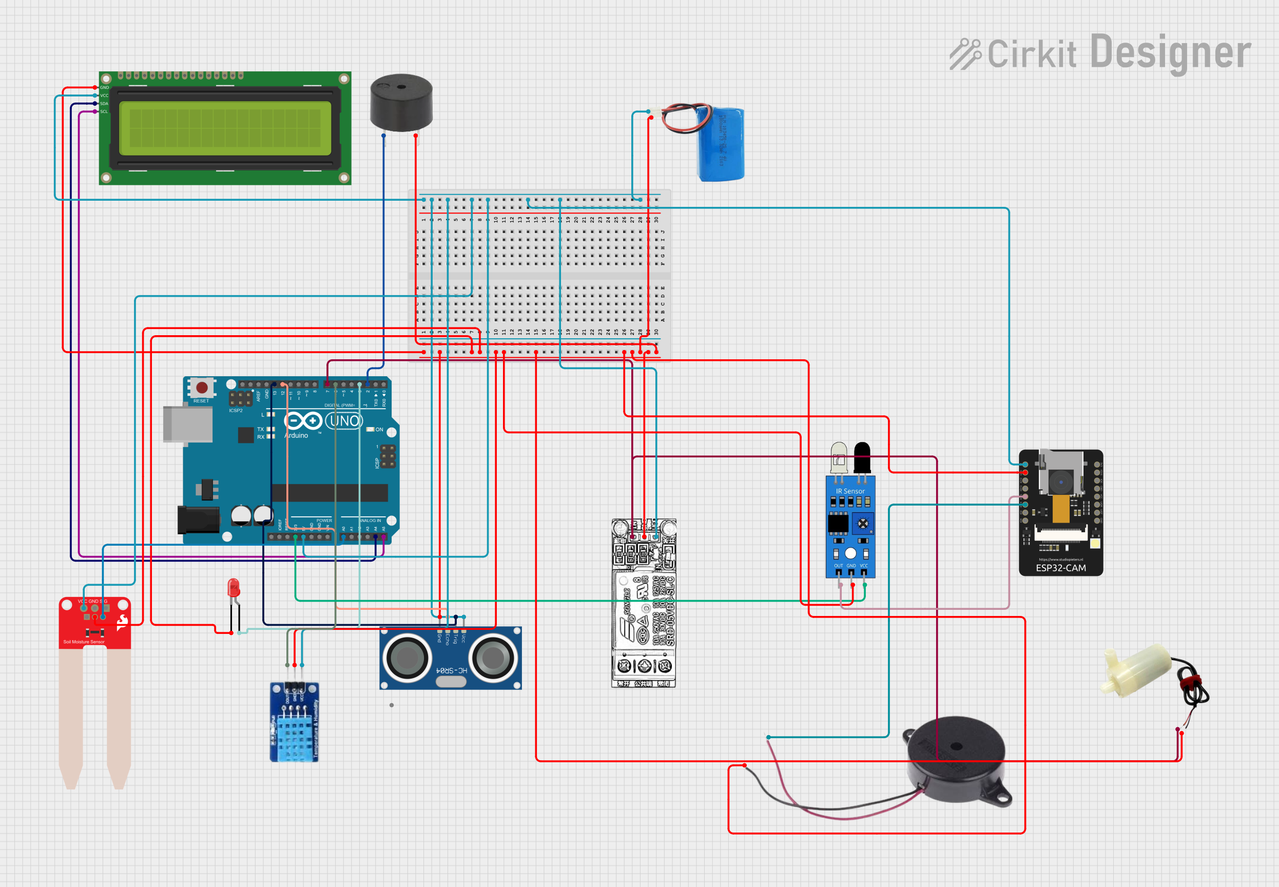
Circuit Documentation
Summary
This document provides a detailed overview of a circuit designed to interface various sensors, actuators, and modules with an Arduino UNO microcontroller and an ESP32-CAM module. The circuit includes components for environmental sensing (soil moisture, temperature, and humidity), distance measurement, visual indication, and actuation (relay control and water pump operation). The Arduino UNO serves as the primary controller, while the ESP32-CAM adds advanced features such as Wi-Fi connectivity and camera functionality.
Component List
- Arduino UNO: A microcontroller board based on the ATmega328P, featuring digital and analog I/O pins.
- Buzzer: An electromechanical component that produces sound when energized.
- SparkFun Soil Moisture Sensor: A sensor that measures the volumetric content of water in the soil.
- HC-SR04 Ultrasonic Sensor: A sensor that measures distance by emitting ultrasonic waves and timing their reflection.
- LED (Red): A two-pin light-emitting diode that emits red light.
- 5V Battery: A power source providing a 5V supply.
- IR Sensor: An infrared sensor used for object detection or distance measurement.
- ESP32-CAM: A small-sized ESP32-based module with Wi-Fi and camera capabilities.
- 16x2 I2C LCD: A liquid crystal display with an I2C interface for displaying text and numbers.
- Relay Module: An electrically operated switch that allows control of a higher power circuit by a low power signal.
- DHT11: A sensor for measuring temperature and humidity.
- 5V Mini Water Pump: A small pump that operates on 5V for moving water.
Wiring Details
Arduino UNO
- 5V: Connected to the 5V power rail supplying power to various components.
- 3.3V: Powers the IR sensor.
- GND: Common ground for the circuit.
- A0: Receives the analog signal from the soil moisture sensor.
- A4 (SDA): I2C data line connected to the 16x2 I2C LCD.
- A5 (SCL): I2C clock line connected to the 16x2 I2C LCD.
- D2: Connected to the buzzer.
- D3: Connected to the anode of the red LED.
- D6: Connected to the data pin of the DHT11 sensor.
- D7: Controls the relay module, which in turn controls the 5V mini water pump.
- D12: Receives the ECHO signal from the HC-SR04 ultrasonic sensor.
- D13: Sends the TRIG signal to the HC-SR04 ultrasonic sensor.
Buzzer
- PIN: Connected to digital pin D2 on the Arduino UNO.
- GND: Connected to the common ground.
SparkFun Soil Moisture Sensor
- VCC: Powered by the 5V rail.
- GND: Connected to the common ground.
- SIG: Outputs an analog signal to A0 on the Arduino UNO.
HC-SR04 Ultrasonic Sensor
- VCC: Powered by the 5V rail.
- TRIG: Connected to digital pin D13 on the Arduino UNO.
- ECHO: Connected to digital pin D12 on the Arduino UNO.
- GND: Connected to the common ground.
LED (Red)
- Anode: Connected to digital pin D3 on the Arduino UNO.
- Cathode: Connected to the common ground.
5V Battery
- Positive: Connected to the 5V power rail.
- Negative: Connected to the common ground.
IR Sensor
- Out: Connected to IO15 on the ESP32-CAM.
- GND: Connected to the common ground.
- VCC: Powered by the 3.3V output from the Arduino UNO.
ESP32-CAM
- 5V: Powered by the 5V rail.
- GND: Connected to the common ground.
- IO15: Receives the output signal from the IR sensor.
- IO14: Connected to the positive pin of the additional buzzer.
16x2 I2C LCD
- GND: Connected to the common ground.
- VCC: Powered by the 5V rail.
- SDA: Connected to A4 (SDA) on the Arduino UNO.
- SCL: Connected to A5 (SCL) on the Arduino UNO.
Relay Module
- VCC: Powered by the 5V rail.
- GND: Connected to the common ground.
- INPUT: Controlled by digital pin D7 on the Arduino UNO.
- COM: Common contact for the relay switch.
- NC: Normally closed contact of the relay.
DHT11
- DATA: Connected to digital pin D6 on the Arduino UNO.
- GND: Connected to the common ground.
- VCC: Powered by the 5V rail.
5V Mini Water Pump
- Positive Pin: Controlled by the relay module.
- Negative Pin: Connected to the common ground.
Documented Code
Arduino UNO Code (sketch.ino)
void setup() {
  // put your setup code here, to run once:

}

void loop() {
  // put your main code here, to run repeatedly:

}
The provided code for the Arduino UNO is a template with empty setup() and loop() functions. The setup() function is intended for initialization code that runs once, such as configuring pin modes. The loop() function is for the main code that runs repeatedly, such as reading sensors, controlling actuators, and communicating with other devices.
ESP32-CAM Code
No code was provided for the ESP32-CAM module. Additional code would be required to utilize its Wi-Fi and camera functionalities.
This documentation provides a foundational overview of the circuit's components, wiring, and code structure. Further details and implementation specifics would be added as the circuit design progresses and the code is developed.