
Arduino UNO-Based Multi-Button Alarm System with LED Indicators and Buzzer
View and Edit Project In Cirkit Designer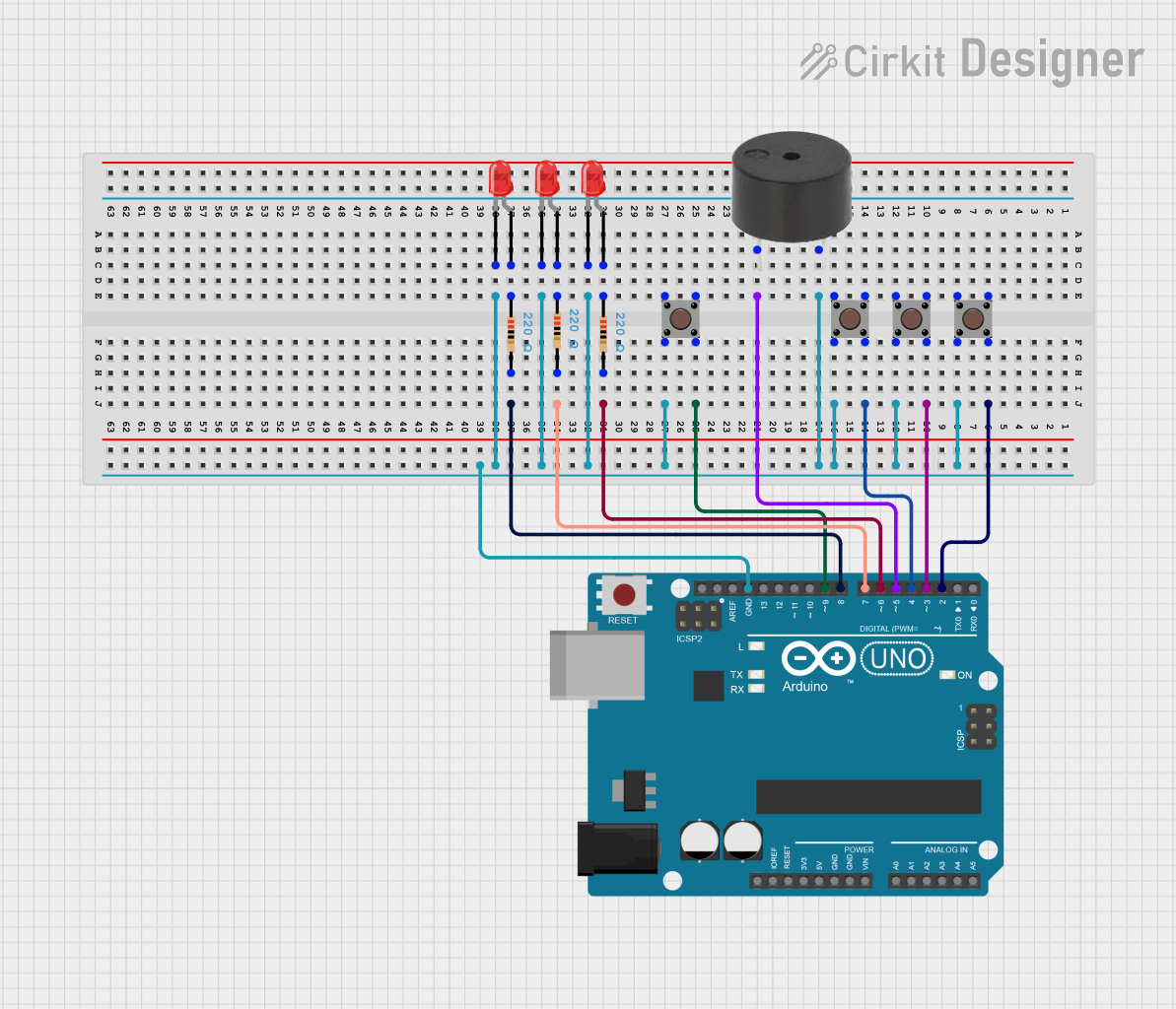
Circuit Documentation
Summary
This circuit is designed to interface with an Arduino UNO microcontroller. It includes four pushbuttons, three LEDs, a buzzer, and three resistors. The pushbuttons are used to control the LEDs and the buzzer, with one button dedicated to resetting the system. The Arduino UNO is programmed to handle the input from the buttons and control the output to the LEDs and the buzzer accordingly.
Component List
Pushbutton
- Description: A simple pushbutton switch.
- Pins: Pin 1 (in), Pin 2 (in), Pin 3 (out), Pin 4 (out)
Arduino UNO
- Description: A microcontroller board based on the ATmega328P.
- Pins: UNUSED, IOREF, Reset, 3.3V, 5V, GND, Vin, A0, A1, A2, A3, A4, A5, SCL, SDA, AREF, D13, D12, D11, D10, D9, D8, D7, D6, D5, D4, D3, D2, D1, D0
Buzzer
- Description: An electronic device that produces a sound.
- Pins: PIN, GND
LED: Two Pin (red)
- Description: A red light-emitting diode.
- Pins: cathode, anode
Resistor
- Description: A passive electrical component with a resistance of 220 Ohms.
- Pins: pin1, pin2
Wiring Details
Pushbutton 1
- Pin 4 (out) connected to Arduino UNO D2
- Pin 2 (in) connected to:
- Pushbutton 2 Pin 2 (in)
- Pushbutton 3 Pin 2 (in)
- Pushbutton 4 Pin 2 (in)
- Buzzer GND
- LED 1 cathode
- LED 2 cathode
- LED 3 cathode
- Arduino UNO GND
Pushbutton 2
- Pin 4 (out) connected to Arduino UNO D3
Pushbutton 3
- Pin 4 (out) connected to Arduino UNO D4
Pushbutton 4
- Pin 4 (out) connected to Arduino UNO D9
Buzzer
- PIN connected to Arduino UNO D5
- GND connected to:
- Pushbutton 1 Pin 2 (in)
- Pushbutton 2 Pin 2 (in)
- Pushbutton 3 Pin 2 (in)
- Pushbutton 4 Pin 2 (in)
- LED 1 cathode
- LED 2 cathode
- LED 3 cathode
- Arduino UNO GND
LED 1
- cathode connected to:
- Pushbutton 1 Pin 2 (in)
- Pushbutton 2 Pin 2 (in)
- Pushbutton 3 Pin 2 (in)
- Pushbutton 4 Pin 2 (in)
- Buzzer GND
- LED 2 cathode
- LED 3 cathode
- Arduino UNO GND
- anode connected to Resistor 1 pin1
LED 2
- cathode connected to:
- Pushbutton 1 Pin 2 (in)
- Pushbutton 2 Pin 2 (in)
- Pushbutton 3 Pin 2 (in)
- Pushbutton 4 Pin 2 (in)
- Buzzer GND
- LED 1 cathode
- LED 3 cathode
- Arduino UNO GND
- anode connected to Resistor 2 pin1
LED 3
- cathode connected to:
- Pushbutton 1 Pin 2 (in)
- Pushbutton 2 Pin 2 (in)
- Pushbutton 3 Pin 2 (in)
- Pushbutton 4 Pin 2 (in)
- Buzzer GND
- LED 1 cathode
- LED 2 cathode
- Arduino UNO GND
- anode connected to Resistor 3 pin1
Resistor 1
- pin1 connected to LED 1 anode
- pin2 connected to Arduino UNO D6
Resistor 2
- pin1 connected to LED 2 anode
- pin2 connected to Arduino UNO D7
Resistor 3
- pin1 connected to LED 3 anode
- pin2 connected to Arduino UNO D8
Code Documentation
// Pin Definitions
#define BUTTON1 2
#define BUTTON2 3
#define BUTTON3 4
#define BUTTON4 9  // Reset button
#define BUZZER_PIN 5
#define LED1 6
#define LED2 7
#define LED3 8
#define LED4 10  // Reset LED

// Flag variable to track reset state
bool resetFlag = false;

void setup() {
  // Initialize LED pins as output
  pinMode(LED1, OUTPUT);
  pinMode(LED2, OUTPUT);
  pinMode(LED3, OUTPUT);
  pinMode(LED4, OUTPUT);

  // Initialize button pins as input with internal pull-up resistors
  pinMode(BUTTON1, INPUT_PULLUP);
  pinMode(BUTTON2, INPUT_PULLUP);
  pinMode(BUTTON3, INPUT_PULLUP);
  pinMode(BUTTON4, INPUT_PULLUP);

  // Initialize buzzer pin as output
  pinMode(BUZZER_PIN, OUTPUT);

  // Turn off all LEDs at the start
  digitalWrite(LED1, LOW);
  digitalWrite(LED2, LOW);
  digitalWrite(LED3, HIGH);  // Default state: LED3 ON
  digitalWrite(LED4, LOW);
}

void loop() {
  // Check if reset button (BUTTON4) is pressed
  if (digitalRead(BUTTON4) == LOW) {
    resetFlag = true;
    digitalWrite(LED4, HIGH);  // Turn on reset LED
    delay(200);                // Debounce delay
    resetFlag = false;
    resetSystem();             // Reset the system
  }

  // If resetFlag is not set, check other buttons
  if (!resetFlag) {
    if (digitalRead(BUTTON1) == LOW) {
      indicateButtonPress(1);
    } else if (digitalRead(BUTTON2) == LOW) {
      indicateButtonPress(2);
    } else if (digitalRead(BUTTON3) == LOW) {
      indicateButtonPress(3);
    } else {
      setDefaultState();  // Default state when no buttons are pressed
    }
  }
}

// Function to indicate button press with corresponding LED states
void indicateButtonPress(int buttonNumber) {
  switch (buttonNumber) {
    case 1:
      digitalWrite(LED1, HIGH);
      digitalWrite(LED2, LOW);
      digitalWrite(LED3, LOW);
      break;
    case 2:
      digitalWrite(LED1, LOW);
      digitalWrite(LED2, HIGH);
      digitalWrite(LED3, LOW);
      break;
    case 3:
      digitalWrite(LED1, HIGH);
      digitalWrite(LED2, HIGH);
      digitalWrite(LED3, LOW);
      break;
  }
  Alarm();  // Sound the alarm
  waitForReset();  // Wait for reset button press
}

// Function to set default state (LED3 ON)
void setDefaultState() {
  digitalWrite(LED1, LOW);
  digitalWrite(LED2, LOW);
  digitalWrite(LED3, HIGH);
}

// Function to sound the alarm
void Alarm() {
  for (int i = 0; i < 100; i++) {
    digitalWrite(BUZZER_PIN, HIGH);
    delay(2);
    digitalWrite(BUZZER_PIN, LOW);
    delay(2);
  }
}

// Function to reset the system
void resetSystem() {
  digitalWrite(LED1, LOW);
  digitalWrite(LED2, LOW);
  digitalWrite(LED3, HIGH);  // Default state: LED3 ON
  digitalWrite(LED4, LOW);   // Turn off reset LED
}

// Function to wait until the reset button (BUTTON4) is pressed
void waitForReset() {
  while (digitalRead(BUTTON4) == HIGH) {
    // Do nothing, wait for the reset button to be pressed
  }
  delay(200);  // Debounce delay
  resetSystem();  // Reset the system once the button is released
}
This code is designed to control the LEDs and the buzzer based on the input from the pushbuttons. The reset button (BUTTON4) resets the system to its default state. The other buttons (BUTTON1, BUTTON2, BUTTON3) control the LEDs and sound the buzzer when pressed.