Arduino and GSM-Based Power Monitoring and Wi-Fi Controlled Lighting System
Circuit Documentation
Summary
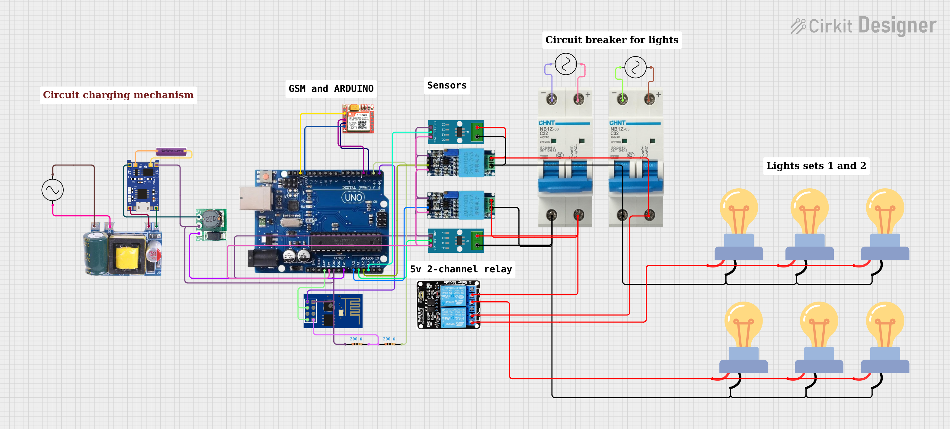
The circuit in question is designed to monitor voltage and current using sensor modules, control lighting via relay modules, and communicate alerts and status through GSM and WiFi modules. It includes an Arduino Uno R3 as the central microcontroller, which processes sensor data and controls peripherals. The circuit features current sensors (ACS712), voltage sensors, LED bulbs for lighting, a circuit breaker for protection, an AC supply as the power source, a relay module for controlling the lights, a GSM module (sim 800l) for cellular communication, a WiFi module (ESP8266 ESP-01) for wireless connectivity, a mini AC-DC converter module, a TP4056 for battery charging, a step-up boost converter, and a 3.7V battery. Additionally, resistors are included for current limiting or voltage division as needed.
Component List
ACS712 Current Sensor
- Description: A current sensor module capable of measuring AC or DC currents.
- Pins: 1, 2, GND, OUT, VCC
Voltage Sensor
- Description: A module for measuring AC or DC voltage levels.
- Pins: Ground, Phase, Vcc, Out, Gnd
LED Bulb AC
- Description: An AC-powered LED bulb for lighting purposes.
- Pins: +, -
AC Supply
- Description: The main power source for the circuit, providing AC voltage.
- Pins: +ve, -ve
Circuit Breaker
- Description: A safety device used to protect the circuit from overcurrent conditions.
- Pins: -, +
5V 2-Relay Module (JD-VCC)
- Description: A relay module with two channels, used for switching high power devices.
- Pins: JD-VCC, VCC, GND, IN1, IN2, NO, COM, NC
SIM800L GSM Module
- Description: A GSM module for cellular network communication.
- Pins: NFT, RING, VCC, DTR, RST, MIC +, RXD, MIC-, TXD, SPK+, GND, SPK-
Mini AC-DC 110V-230V to 5V 700mA Module
- Description: A power supply module that converts AC to 5V DC.
- Pins: GND, 5v, Neutral, Life
TP4056
- Description: A lithium battery charging module.
- Pins: OUT-, B-, B+, OUT+, IN-, IN+
Arduino Uno R3
- Description: A microcontroller board based on the ATmega328P.
- Pins: USB Port, Power Jack, Not Connected, IOREF, RESET, 3.3V, 5V, GND, VIN, A0-A5, SCL, SDA, AREF, Digital I/O pins 0-13
ESP8266 ESP-01 WiFi Module
- Description: A WiFi module for wireless communication.
- Pins: TXD, CH_PD, RST, VCC, GND, GPIO_2, GPIO_0, RXD
Step Up Boost 3V-5V
- Description: A boost converter module that steps up voltage from 3V to 5V.
- Pins: Vi, GND, Vo
3.7V Battery
- Description: A rechargeable lithium battery providing 3.7V.
- Pins: +, -
Resistor
- Description: A passive two-terminal electrical component that implements electrical resistance.
- Pins: pin1, pin2
- Properties: Resistance value of 200 Ohms
Wiring Details
ACS712 Current Sensor
- 1, 2: Connected to the circuit under test for current measurement.
- GND: Connected to the common ground.
- OUT: Output connected to an analog input on the Arduino Uno R3 for current measurement.
- VCC: Power supply input, connected to a 5V source.
Voltage Sensor
- Ground, Gnd: Connected to the common ground.
- Phase: Connected to the voltage source under test.
- Vcc: Power supply input, connected to a 5V source.
- Out: Output connected to an analog input on the Arduino Uno R3 for voltage measurement.
LED Bulb AC
- +: Connected to the normally open (NO) terminal of the relay module.
- -: Connected to the common ground or negative terminal of the AC supply.
AC Supply
- +ve: Positive terminal connected to the circuit breaker and relay module.
- -ve: Negative terminal connected to the common ground or negative side of the circuit.
Circuit Breaker
- +: Connected to the positive terminal of the AC supply.
- -: Connected to the negative terminal of the AC supply and the negative side of the circuit.
5V 2-Relay Module (JD-VCC)
- JD-VCC: Relay power supply, connected to a 5V source.
- VCC: Control circuit power supply, connected to a 5V source.
- GND: Connected to the common ground.
- IN1, IN2: Control inputs connected to digital outputs on the Arduino Uno R3.
- NO, COM, NC: Relay switch terminals, NO connected to the LED bulbs, COM connected to the AC supply.
SIM800L GSM Module
- VCC: Power supply input, connected to a 5V source.
- GND: Connected to the common ground.
- RXD, TXD: Serial communication pins, connected to digital pins on the Arduino Uno R3.
Mini AC-DC 110V-230V to 5V 700mA Module
- GND: Connected to the common ground.
- 5v: 5V DC output, connected to the TP4056 module and other 5V inputs.
- Neutral, Life: AC input terminals, connected to the AC supply.
TP4056
- IN-, IN+: Charging input, connected to the Mini AC-DC module.
- OUT-, OUT+: Charging output, connected to the Step Up Boost module.
- B-, B+: Battery connections, connected to the 3.7V battery.
ESP8266 ESP-01 WiFi Module
- VCC: Power supply input, connected to a 5V source.
- GND: Connected to the common ground.
- CH_PD: Chip enable, connected to 5V.
- TXD, RXD: Serial communication pins, connected to digital pins on the Arduino Uno R3.
Step Up Boost 3V-5V
- Vi: Input voltage, connected to the OUT+ of the TP4056 module.
- GND: Connected to the common ground.
- Vo: Output voltage, connected to the VIN pin on the Arduino Uno R3.
3.7V Battery
- +: Connected to the B+ of the TP4056 module.
- -: Connected to the B- of the TP4056 module.
Resistor
- pin1, pin2: Connected in series with the RXD pin of the ESP8266 and the Arduino Uno R3 to limit current or voltage.
Documented Code
Arduino Uno R3 Code
/*
 * This Arduino Sketch reads voltage and current from two sets of sensors,
 * calculates power, and sends alerts via GSM if power is below a threshold.
 * It also connects to WiFi using ESP-01 and controls lights via a relay module.
 */

#include <SoftwareSerial.h>
#include <ESP8266WiFi.h>

// Pin definitions
#define VOLTAGE_SENSOR_1 A0
#define CURRENT_SENSOR_1 A1
#define VOLTAGE_SENSOR_2 A2
#define CURRENT_SENSOR_2 A3
#define RELAY_1 7
#define RELAY_2 8
#define GSM_TX 2
#define GSM_RX 3
#define ESP_TX 4
#define ESP_RX 5

// Predefined power values
const float PDF_power_1 = 500.0;
const float PDF_power_2 = 500.0;

// Threshold for alert
const float POWER_THRESHOLD = 400.0;

// GSM and WiFi credentials
const char* phoneNumber = "+237671693917";
const char* ssid = "suh";
const char* password = "davadeli2";

// Software serial for GSM and ESP
SoftwareSerial gsmSerial(GSM_RX, GSM_TX);
SoftwareSerial espSerial(ESP_RX, ESP_TX);

void setup() {
  // Initialize serial communication
  Serial.begin(9600);
  gsmSerial.begin(9600);
  espSerial.begin(9600);

  // Initialize pins
  pinMode(RELAY_1, OUTPUT);
  pinMode(RELAY_2, OUTPUT);
  digitalWrite(RELAY_1, LOW);
  digitalWrite(RELAY_2, LOW);

  // Connect to WiFi
  connectToWiFi();
}

void loop() {
  // Read sensors
  float voltage1 = analogRead(VOLTAGE_SENSOR_1) * (5.0 / 1023.0);
  float current1 = analogRead(CURRENT_SENSOR_1) * (5.0 / 1023.0);
  float voltage2 = analogRead(VOLTAGE_SENSOR_2) * (5.0 / 1023.0);
  float current2 = analogRead(CURRENT_SENSOR_2) * (5.0 / 1023.0);

  // Calculate power
  float power1 = voltage1 * current1;
  float power2 = voltage2 * current2;

  // Check power and send alert if below threshold
  if (power1 < POWER_THRESHOLD)