
ESP32-Based Ultrasonic Distance Measurement with LED Indicators
View and Edit Project In Cirkit Designer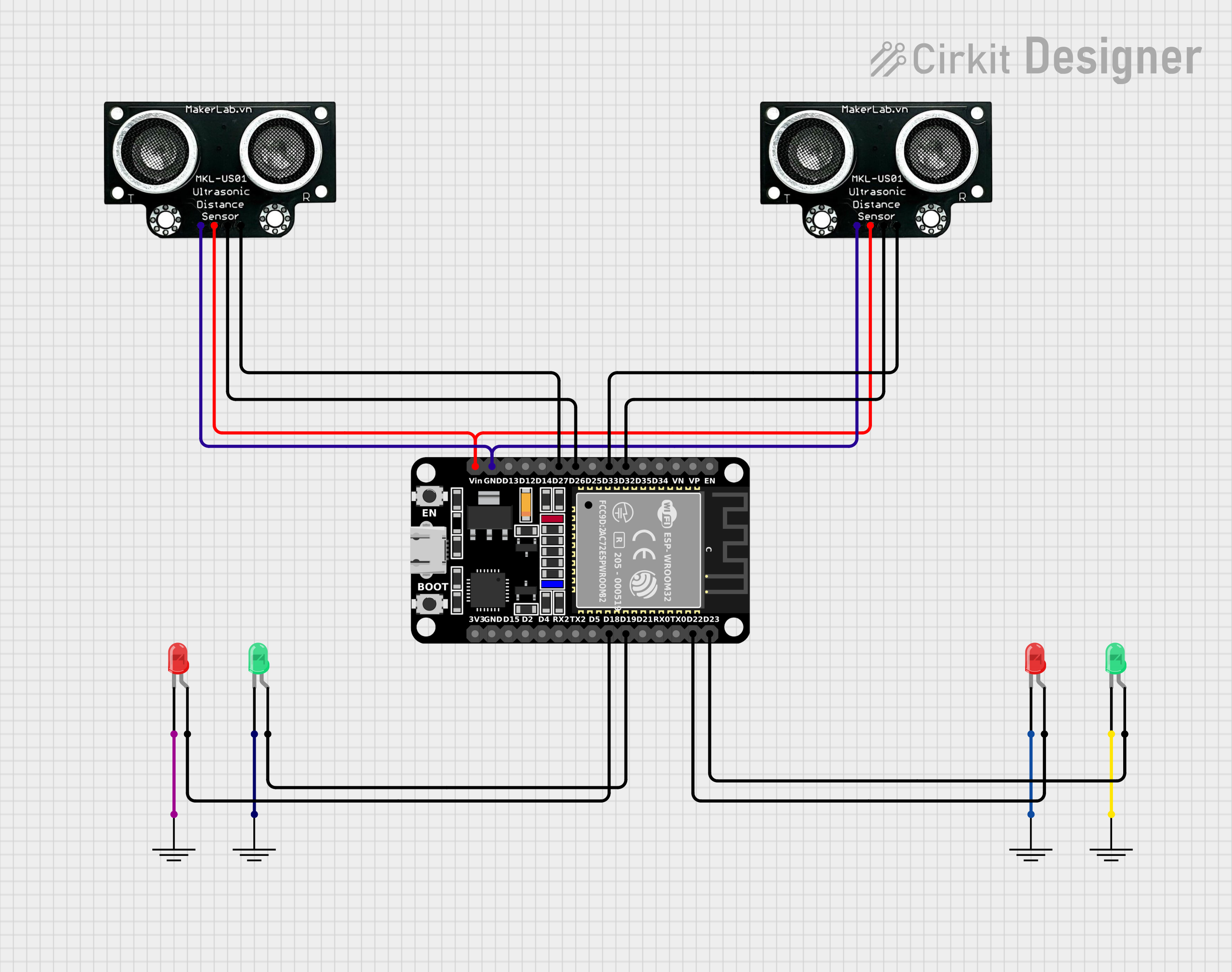
Circuit Documentation
Summary of the Circuit
This circuit is designed to interface an ESP32 microcontroller with two MKE-S01 Ultrasonic Distance Sensors and four LEDs (two red and two green). The ESP32 is used to control the ultrasonic sensors and LEDs. The ultrasonic sensors are likely used for distance measurement, while the LEDs may serve as indicators for certain distance thresholds or operational status.
Component List
ESP32 (30 pin)
- Description: A microcontroller with Wi-Fi and Bluetooth capabilities, featuring a wide range of GPIO pins.
- Purpose: Acts as the central processing unit of the circuit, controlling the ultrasonic sensors and LEDs.
MKE-S01 Ultrasonic Distance Sensor
- Description: A sensor that measures distance by emitting ultrasonic waves and measuring the time taken for the echo to return.
- Purpose: Used for measuring distances in the circuit. There are two instances of this sensor in the circuit.
LED: Two Pin (red)
- Description: A basic red LED with an anode and cathode.
- Purpose: Serves as an indicator light. There are two instances of this red LED in the circuit.
LED: Two Pin (green)
- Description: A basic green LED with an anode and cathode.
- Purpose: Serves as an indicator light. There are two instances of this green LED in the circuit.
GND
- Description: A ground reference point for the circuit.
- Purpose: Provides a common ground for the circuit components. There are multiple instances of this ground reference in the circuit.
Wiring Details
ESP32 (30 pin)
- Pin D32 connected to Ultrasonic Sensor (TRIG)
- Pin D33 connected to Ultrasonic Sensor (ECHO)
- Pin D26 connected to Ultrasonic Sensor (TRIG)
- Pin D27 connected to Ultrasonic Sensor (ECHO)
- Pin GND connected to Ultrasonic Sensor (GND)
- Pin Vin connected to Ultrasonic Sensor (5V)
- Pin D23 connected to Green LED (anode)
- Pin D22 connected to Red LED (anode)
- Pin D19 connected to Green LED (anode)
- Pin D18 connected to Red LED (anode)
MKE-S01 Ultrasonic Distance Sensor
- TRIG pin connected to ESP32 (D32 or D26)
- ECHO pin connected to ESP32 (D33 or D27)
- GND pin connected to ESP32 (GND)
- 5V pin connected to ESP32 (Vin)
LED: Two Pin (red)
- Anode connected to ESP32 (D22 or D18)
- Cathode connected to GND
LED: Two Pin (green)
- Anode connected to ESP32 (D23 or D19)
- Cathode connected to GND
GND
- GND pin connected to LED cathodes and Ultrasonic Sensor GND pins
Documented Code
Since no code was provided in the input, this section cannot be completed. Normally, this section would include the source code for the microcontroller, with comments explaining the functionality of each part of the code. It would also detail how the code interacts with the hardware components listed above, such as how it triggers the ultrasonic sensors and controls the LEDs based on the sensor readings.