Cirkit Designer
Your all-in-one circuit design IDE
Home /
Project Documentation
Arduino UNO-Based IR-Controlled LCD Display with DC Motor
Circuit Documentation
Summary
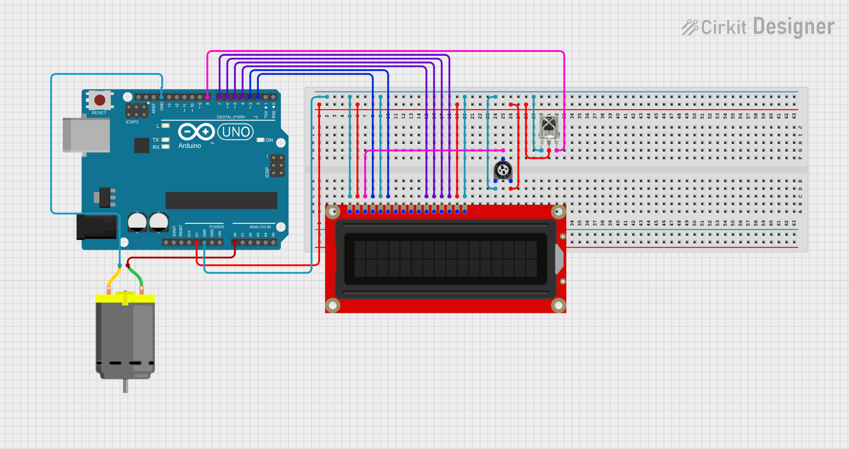
This circuit involves an Arduino UNO microcontroller, a DC motor, an LCD screen, a trimmer potentiometer, and a VS1838B IR receiver. The Arduino UNO serves as the central controller, interfacing with the other components to control the motor, display information on the LCD screen, and receive IR signals.
Component List
Arduino UNO
- Description: A microcontroller board based on the ATmega328P.
- Pins: UNUSED, IOREF, Reset, 3.3V, 5V, GND, Vin, A0, A1, A2, A3, A4, A5, SCL, SDA, AREF, D13, D12, D11, D10, D9, D8, D7, D6, D5, D4, D3, D2, D1, D0
DC Motor
- Description: A simple DC motor.
- Pins: pin 1, pin 2
LCD Screen
- Description: A standard LCD screen for displaying information.
- Pins: Backlight (GND), VSS, VDD, Contrast, RS, E, R/W, D0, D1, D2, D3, D4, D5, D6, D7, Backlight_PWR
Trimmer Potentiometer
- Description: A variable resistor used to adjust the contrast of the LCD screen.
- Pins: leg1, wiper, leg2
- Properties:
- Resistance: 10000 Ohms
VS1838B IR Receiver
- Description: An IR receiver module for receiving infrared signals.
- Pins: OUT, GND, VCC
Wiring Details
Arduino UNO
- GND: Connected to LCD screen (VSS, R/W, Backlight (GND)), Trimmer Potentiometer (leg1), VS1838B IR Receiver (OUT), DC Motor (pin 2)
- 5V: Connected to LCD screen (VDD, Backlight_PWR), Trimmer Potentiometer (leg2), VS1838B IR Receiver (GND)
- D2: Connected to LCD screen (RS)
- D3: Connected to LCD screen (E)
- D4: Connected to LCD screen (D4)
- D5: Connected to LCD screen (D5)
- D6: Connected to LCD screen (D6)
- D7: Connected to LCD screen (D7)
- D8: Connected to VS1838B IR Receiver (VCC)
- A0: Connected to DC Motor (pin 1)
DC Motor
- pin 1: Connected to Arduino UNO (A0)
- pin 2: Connected to Arduino UNO (GND)
LCD Screen
- VSS: Connected to Arduino UNO (GND)
- R/W: Connected to Arduino UNO (GND)
- Backlight (GND): Connected to Arduino UNO (GND)
- VDD: Connected to Arduino UNO (5V)
- Backlight_PWR: Connected to Arduino UNO (5V)
- Contrast: Connected to Trimmer Potentiometer (wiper)
- RS: Connected to Arduino UNO (D2)
- E: Connected to Arduino UNO (D3)
- D4: Connected to Arduino UNO (D4)
- D5: Connected to Arduino UNO (D5)
- D6: Connected to Arduino UNO (D6)
- D7: Connected to Arduino UNO (D7)
Trimmer Potentiometer
- leg1: Connected to Arduino UNO (GND)
- wiper: Connected to LCD screen (Contrast)
- leg2: Connected to Arduino UNO (5V)
VS1838B IR Receiver
- OUT: Connected to Arduino UNO (GND)
- GND: Connected to Arduino UNO (5V)
- VCC: Connected to Arduino UNO (D8)
Documented Code
Arduino UNO Code (sketch.ino)
void setup() {
  // put your setup code here, to run once:

}

void loop() {
  // put your main code here, to run repeatedly:

}
Additional Documentation (documentation.txt)
This documentation provides a comprehensive overview of the circuit, including a summary, detailed component list, wiring details, and the code used in the Arduino UNO microcontroller.