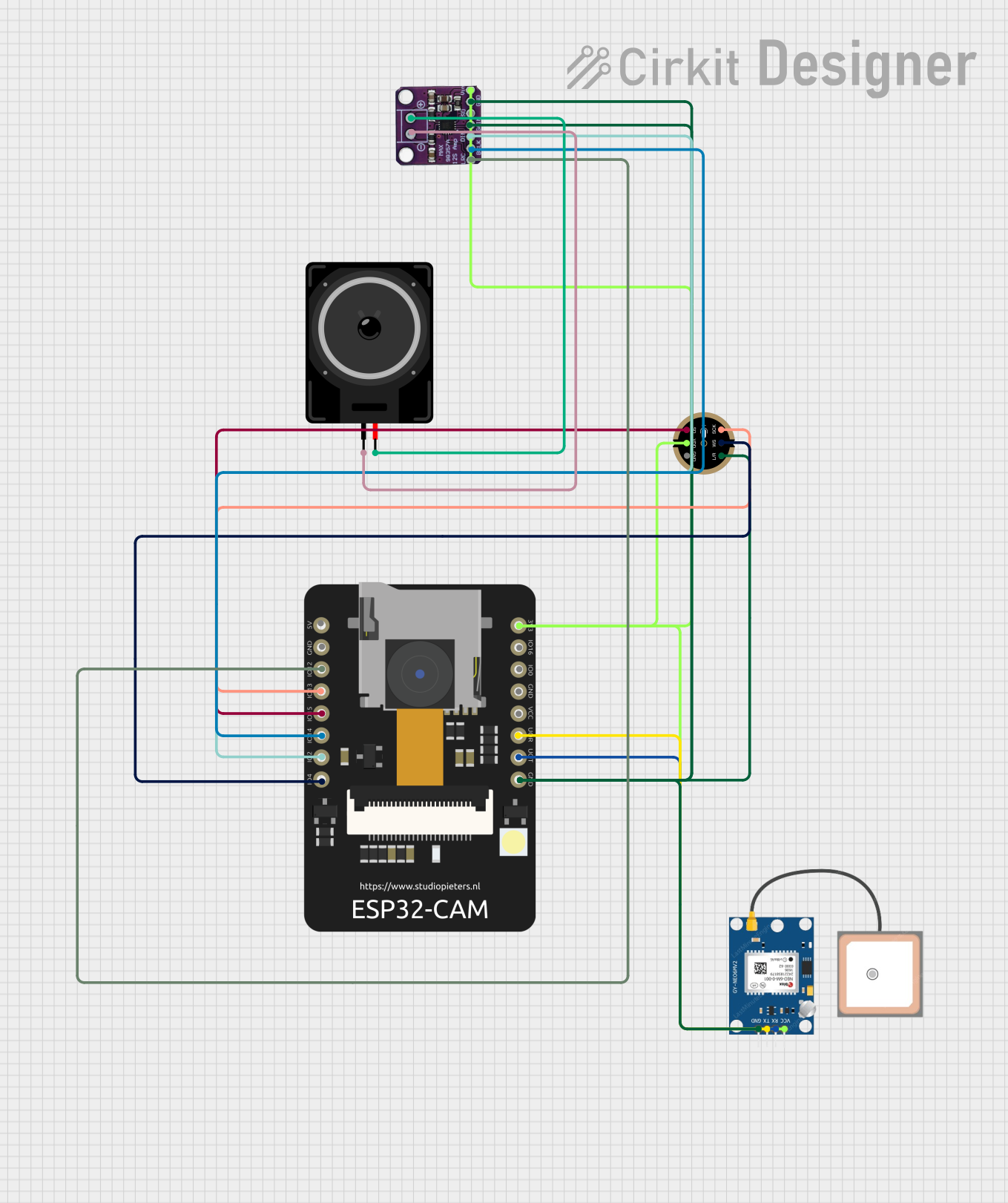
ESP32 CAM-Based Audio-GPS Tracking System

Circuit Documentation
Summary of the Circuit
This circuit integrates a GPS module (GPS NEO 6M), a digital microphone (INMP441 FRONT MIC), an I2S class-D audio amplifier (Max98357), a loudspeaker, and an ESP32 CAM microcontroller module. The ESP32 CAM serves as the central processing unit, interfacing with the GPS module for location data, the microphone for audio input, and the audio amplifier for sound output. The circuit is designed to capture audio and location data, process this information, and output sound through the loudspeaker.
Component List
GPS NEO 6M
- Description: A GPS module capable of providing geolocation data.
- Pins: VCC, RX, TX, GND
INMP441 FRONT MIC
- Description: A digital I2S microphone for capturing high-quality audio.
- Pins: L/R, WS, SCK, SD, VDD, GND
Max98357
- Description: An I2S class-D audio amplifier for driving speakers.
- Pins: LRC, BLCK, DIN, GAIN, SD, GND, VIN, -, +
Loudspeaker
- Description: An electroacoustic transducer used to produce sound.
- Pins: pin1, pin2
ESP32 CAM
- Description: A microcontroller module with Wi-Fi, Bluetooth capabilities, and a camera interface.
- Pins: 5V, GND, GPIO12, GPIO13, GPIO15, GPIO14, GPIO2, GPIO4, 3.3V, GPIO16, GPIO0, 3.3V / 5V / P_OUT, GPIO3 / RX, GPIO1 / TX
Wiring Details
GPS NEO 6M
- VCC: Connected to the 3.3V power supply.
- RX: Connected to GPIO1 / TX of the ESP32 CAM.
- TX: Connected to GPIO3 / RX of the ESP32 CAM.
- GND: Connected to the common ground.
INMP441 FRONT MIC
- L/R: Not connected in this circuit.
- WS: Connected to GPIO4 of the ESP32 CAM.
- SCK: Connected to GPIO13 of the ESP32 CAM.
- SD: Connected to GPIO15 of the ESP32 CAM.
- VDD: Connected to the 3.3V power supply.
- GND: Connected to the common ground.
Max98357
- LRC: Connected to GPIO12 of the ESP32 CAM.
- BLCK: Connected to GPIO14 of the ESP32 CAM.
- DIN: Connected to GPIO2 of the ESP32 CAM.
- GAIN: Not connected in this circuit.
- SD: Not connected in this circuit.
- GND: Connected to the common ground.
- VIN: Connected to the 3.3V power supply.
- -: Connected to pin1 of the Loudspeaker.
- +: Connected to pin2 of the Loudspeaker.
Loudspeaker
- pin1: Connected to the - pin of Max98357.
- pin2: Connected to the + pin of Max98357.
ESP32 CAM
- 3.3V: Provides power to the GPS NEO 6M, INMP441 FRONT MIC, and Max98357.
- GND: Common ground for all components.
- GPIO12: Connected to LRC of Max98357.
- GPIO13: Connected to SCK of INMP441 FRONT MIC.
- GPIO15: Connected to SD of INMP441 FRONT MIC.
- GPIO14: Connected to BLCK of Max98357.
- GPIO2: Connected to DIN of Max98357.
- GPIO4: Connected to WS of INMP441 FRONT MIC.
- GPIO1 / TX: Connected to RX of GPS NEO 6M.
- GPIO3 / RX: Connected to TX of GPS NEO 6M.
Documented Code
No code has been provided for the microcontrollers in the circuit. The ESP32 CAM module would typically be programmed to handle the interfacing with the GPS module, processing audio data from the microphone, and controlling the audio output through the Max98357 amplifier to the loudspeaker. Without the code, we cannot document the specific functionalities or the software architecture implemented in this circuit.