
ESP32-Controlled Robotics Platform with Ultrasonic Sensing and Water Level Detection
View and Edit Project In Cirkit Designer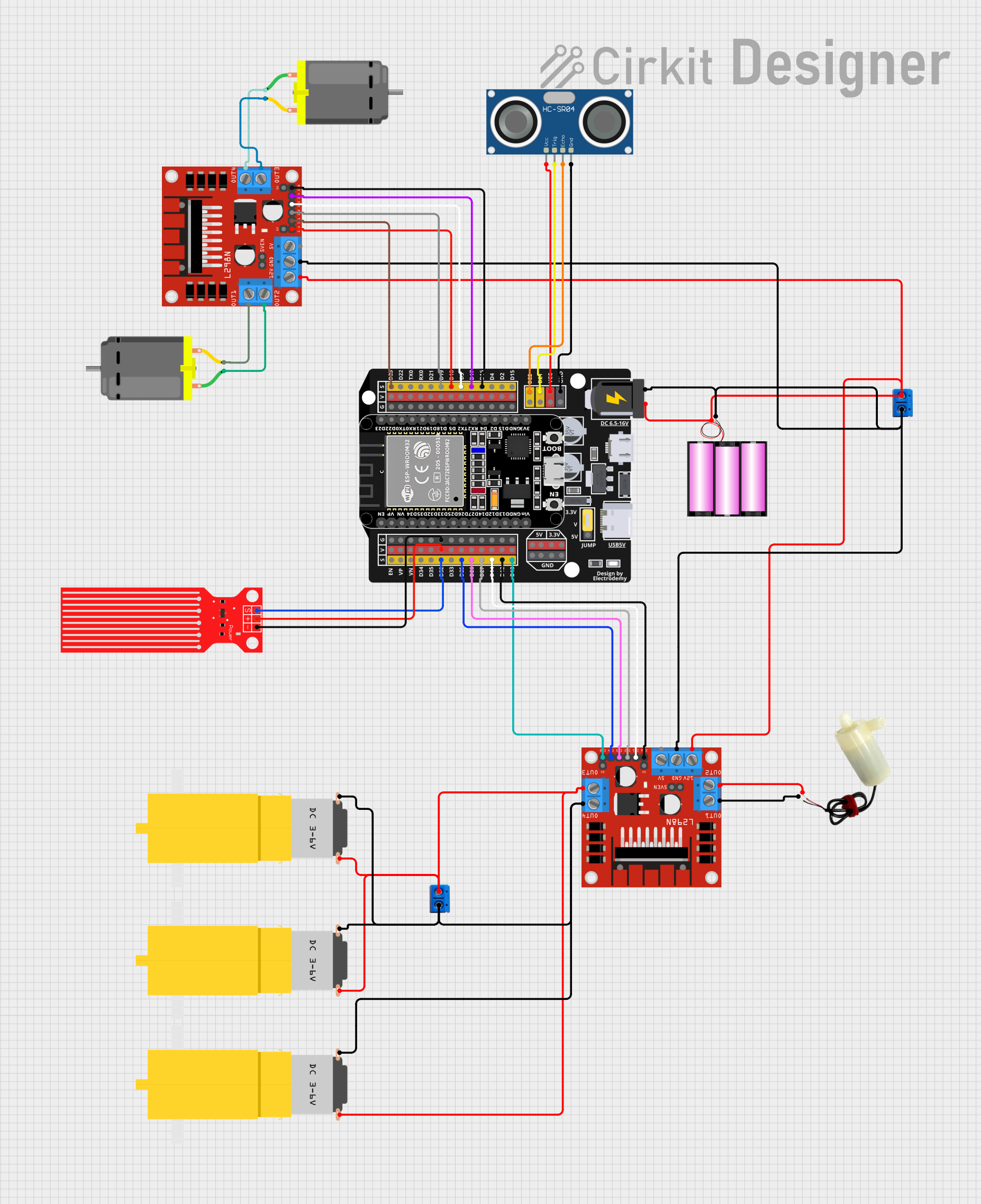
Circuit Documentation
Summary
This circuit is designed to control multiple DC motors and a mini water pump using two L298N DC motor drivers, which are interfaced with an ESP32 microcontroller. The circuit also includes a 12V battery for power, an HC-SR04 Ultrasonic Sensor for distance measurement, and a Water Level Sensor for detecting the water level. The ESP32 microcontroller is responsible for controlling the operation of the motors and the pump, as well as reading sensor data.
Component List
HC-SR04 Ultrasonic Sensor
- Pins: VCC, TRIG, ECHO, GND
- Description: This sensor is used for measuring distances using ultrasonic waves.
DC Motor
- Pins: pin 1, pin 2
- Description: A standard DC motor used for rotational motion.
Battery 12V
- Pins: +, -
- Description: A 12V battery provides power to the circuit.
L298N DC Motor Driver
- Pins: OUT1, OUT2, 12V, GND, 5V, OUT3, OUT4, 5V-ENA-JMP-I, 5V-ENA-JMP-O, +5V-J1, +5V-J2, ENA, IN1, IN2, IN3, IN4, ENB
- Description: A motor driver module that controls the direction and speed of DC motors.
5V Mini Water Pump
- Pins: positive pin, negative pin
- Description: A small pump used for moving water.
Motor Amarillo Motorreductor Hobby
- Pins: vcc, GND
- Description: A hobby gear motor used for projects requiring torque.
Terminal PCB 2 Pin
- Pins: Pin A, Pin B
- Description: A simple two-pin terminal for connecting wires to the PCB.
Water Level Sensor
- Pins: SIG, VCC, GND
- Description: A sensor used to detect the presence and level of water.
ESP32 - Expansion Board
- Pins: +, -, EN, VP, VN, D34, D32, D33, D25, D26, D27, D14, D12, D13, D23, D22, TX0, RX0, D21, D19, D18, D5, D17, D16, D4, D2, D15, VCC, G, 5V, 3.3V, V
- Description: A microcontroller board based on the ESP32 chip, featuring Wi-Fi and Bluetooth connectivity.
Wiring Details
HC-SR04 Ultrasonic Sensor
- VCC connected to ESP32 Expansion Board VCC
- TRIG connected to ESP32 Expansion Board D21
- ECHO connected to ESP32 Expansion Board D22
- GND connected to ESP32 Expansion Board G
DC Motors
- Motor 1:
- pin 1 connected to L298N DC Motor Driver OUT2
- pin 2 connected to L298N DC Motor Driver OUT1
- Motor 2:
- pin 1 connected to L298N DC Motor Driver OUT4
- pin 2 connected to L298N DC Motor Driver OUT3
Battery 12V
- + connected to Terminal PCB 2 Pin Pin A, L298N DC Motor Driver 12V (both instances)
- - connected to Terminal PCB 2 Pin Pin B, L298N DC Motor Driver GND (both instances)
L298N DC Motor Driver (Instance 1)
- OUT1 connected to 5V Mini Water Pump negative pin
- OUT2 connected to 5V Mini Water Pump positive pin
- OUT3 connected to Terminal PCB 2 Pin Pin A
- OUT4 connected to Terminal PCB 2 Pin Pin B
- ENA connected to ESP32 Expansion Board D12
- IN1 connected to ESP32 Expansion Board D14
- IN2 connected to ESP32 Expansion Board D27
- IN3 connected to ESP32 Expansion Board D26
- IN4 connected to ESP32 Expansion Board D25
- ENB connected to ESP32 Expansion Board D13
L298N DC Motor Driver (Instance 2)
- ENA connected to ESP32 Expansion Board D18
- IN1 connected to ESP32 Expansion Board D23
- IN2 connected to ESP32 Expansion Board D19
- IN3 connected to ESP32 Expansion Board D5
- IN4 connected to ESP32 Expansion Board D17
- ENB connected to ESP32 Expansion Board D16
5V Mini Water Pump
- positive pin connected to L298N DC Motor Driver OUT2
- negative pin connected to L298N DC Motor Driver OUT1
Motor Amarillo Motorreductor Hobby (All Instances)
- vcc connected to Terminal PCB 2 Pin Pin A
- GND connected to Terminal PCB 2 Pin Pin B
Terminal PCB 2 Pin (Instance 1)
- Pin A connected to Battery 12V +, L298N DC Motor Driver 12V
- Pin B connected to Battery 12V -, L298N DC Motor Driver GND
Terminal PCB 2 Pin (Instance 2)
- Pin A connected to L298N DC Motor Driver OUT3
- Pin B connected to L298N DC Motor Driver OUT4
Water Level Sensor
- SIG connected to ESP32 Expansion Board D32
- VCC connected to ESP32 Expansion Board V
- GND connected to ESP32 Expansion Board G
ESP32 - Expansion Board
- + connected to Battery 12V +
- - connected to Battery 12V -
- Other connections as detailed above for each component.
Documented Code
There is no code provided for the microcontroller. The code would typically include initialization of the GPIO pins, setup of the PWM channels for motor speed control, and logic for reading sensor data and controlling the motors and pump based on sensor inputs.