Arduino UNO Based Timer-Controlled Relay with Rotary Encoder and LCD Display
Circuit Documentation
Summary
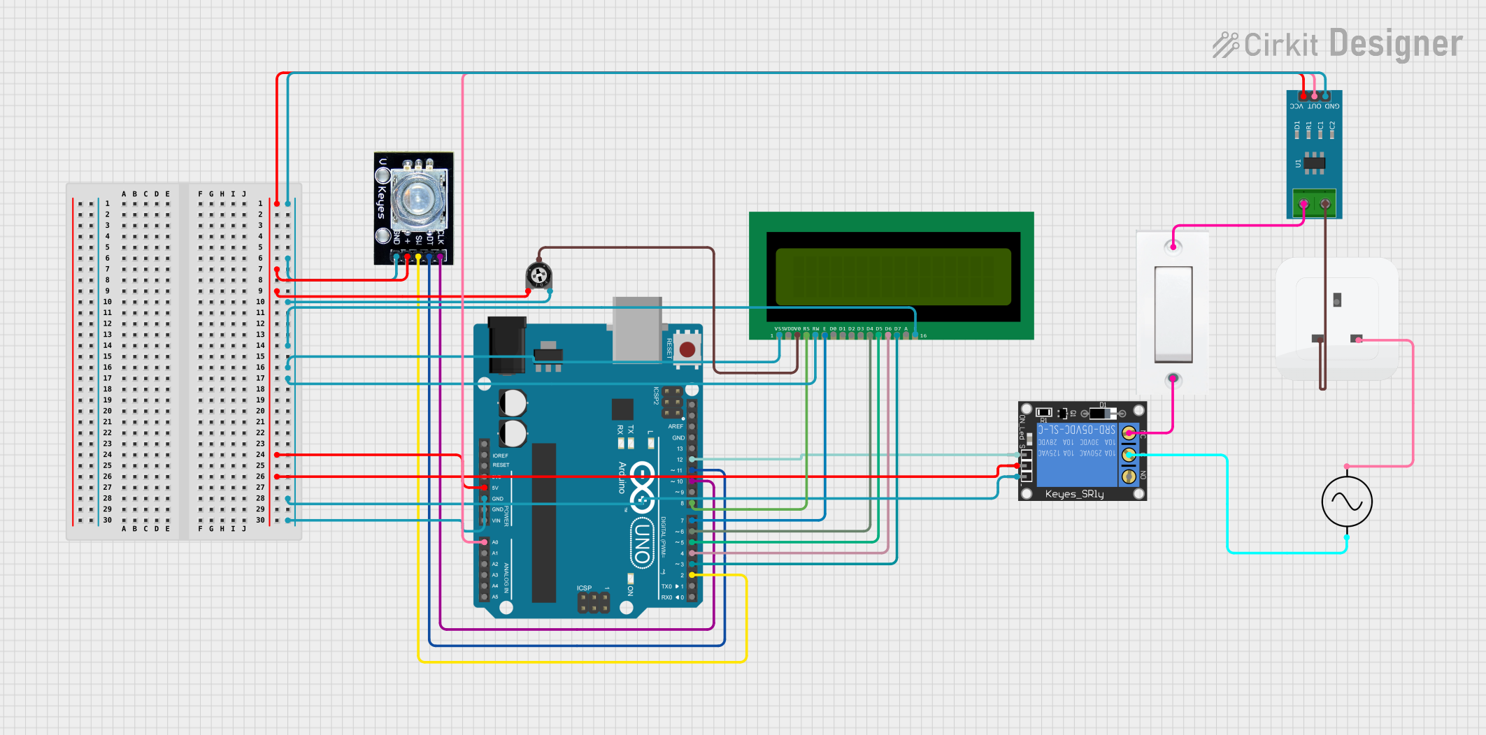
This circuit is designed around an Arduino UNO microcontroller and includes a variety of components such as a rotary encoder, a 16x2 LCD display, a 1-channel relay, a trimmer potentiometer, a current sensor, a socket, a flush switch, and an AC supply. The primary function of this circuit is to control and display a timer, which can be set using the rotary encoder. The timer's countdown is displayed on the LCD, and upon completion, it activates a relay which could control an external device. The current sensor is used to monitor the current flow, and the system's settings can be saved and retrieved from EEPROM.
Component List
- Arduino UNO: A microcontroller board based on the ATmega328P, featuring digital and analog I/O pins.
- Rotary Encoder: An input device that provides rotational position feedback and includes a push-button.
- 16X2 LCD: A liquid crystal display capable of showing 16 characters per line across 2 lines.
- 1-Channel Relay (5V 10A): An electromechanical switch that allows control of a large current circuit by a smaller current signal.
- Trimmer Potentiometer: A variable resistor with three terminals, used to adjust LCD contrast.
- Socket: An electrical component that provides a connection point for an AC power supply.
- Flush Switch: A simple on/off electrical switch.
- AC Supply: A source of alternating current electricity.
- Current Sensor 5A: A device that measures the amount of current flowing through a conductor.
Wiring Details
Arduino UNO
- 5V: Power supply to Current Sensor, Rotary Encoder, Relay
- GND: Common ground for Current Sensor, Rotary Encoder, LCD, Relay
- A0: Connected to the OUT pin of the Current Sensor
- D12: Connected to the signal pin of the Relay
- D11: Connected to the dt pin of the Rotary Encoder
- D10: Connected to the clk pin of the Rotary Encoder
- D8: Connected to the RS pin of the LCD
- D7: Connected to the E pin of the LCD
- D6: Connected to the D4 pin of the LCD
- D5: Connected to the D5 pin of the LCD
- D4: Connected to the D6 pin of the LCD
- D3: Connected to the D7 pin of the LCD
- D2: Connected to the sw pin of the Rotary Encoder
Rotary Encoder
- clk: Connected to D10 on Arduino UNO
- dt: Connected to D11 on Arduino UNO
- sw: Connected to D2 on Arduino UNO
- gnd: Common ground
- +: Power supply from Arduino UNO 5V
16X2 LCD
- VSS, K, RW: Connected to common ground
- VDD: Power supply (not specified in net list)
- V0: Connected to the wiper of the Trimmer Potentiometer
- RS: Connected to D8 on Arduino UNO
- E: Connected to D7 on Arduino UNO
- D4: Connected to D6 on Arduino UNO
- D5: Connected to D5 on Arduino UNO
- D6: Connected to D4 on Arduino UNO
- D7: Connected to D3 on Arduino UNO
1-Channel Relay (5V 10A)
- NC: Connected to the GND of the Flush Switch
- signal: Connected to D12 on Arduino UNO
- C: Connected to the +ve of the AC Supply
- power: Power supply from Arduino UNO 5V
- ground: Common ground
Trimmer Potentiometer
- leg1: Power supply from Arduino UNO 5V
- wiper: Connected to V0 of the LCD
- leg2: Common ground
Socket
- earth: Not connected (not specified in net list)
- life: Connected to pin 2 of the Current Sensor
- neutral: Connected to the -ve of the AC Supply
Flush Switch
- GND: Connected to the NC of the Relay
- VCC: Connected to pin 1 of the Current Sensor
AC Supply
- +ve: Connected to the C of the Relay
- -ve: Connected to the neutral of the Socket
Current Sensor 5A
- VCC: Power supply from Arduino UNO 5V
- GND: Common ground
- OUT: Connected to A0 on Arduino UNO
- 1: Connected to the VCC of the Flush Switch
- 2: Connected to the life of the Socket
Documented Code
#include<LiquidCrystal.h>
#include<EEPROM.h>
LiquidCrystal lcd (8,7,6,5,4,3);
#define outputA 10 //clk pin of rotary encoder
#define outputB 11 //dt pin of rotary encoder
#define button 2   //sw pin of rotary encoder
#define led 13     //status led
#define relay 12   //in1 of relay

int count = 1;
int current_state;
int previous_state;
int hh =0;
int mm=0;
int ss=0;
int h=0;
int m=0;
int s=0;
int ledToggle;
int previousState = HIGH;
unsigned int previousPress;
volatile int buttonFlag;
int buttonDebounce = 20;

void setup()
{
  lcd.begin(16,2);
  pinMode (outputA,INPUT);
  pinMode (outputB,INPUT);
  pinMode (button,INPUT_PULLUP);
  pinMode (led, OUTPUT);
  pinMode (relay, OUTPUT);
  digitalWrite(relay, HIGH);
  attachInterrupt(digitalPinToInterrupt(2), button_ISR, CHANGE);
  Serial.begin (9600);
  previous_state = digitalRead(outputA);
}

void loop()
{
  encoder();
  // The rest of the loop code handles the user interface and timer logic
}

void encoder (void)
{
  // This function reads the rotary encoder position and updates the count
}

void button_ISR()
{
  // This interrupt service routine handles the button press event
}

void timer (void)
{
  // This function handles the countdown timer logic and display
}
Note: The code provided above is a partial representation of the full code. The full code includes functions for handling the rotary encoder input, button press interrupts, and the countdown timer logic. The code also includes EEPROM read/write operations to save and retrieve the timer settings.