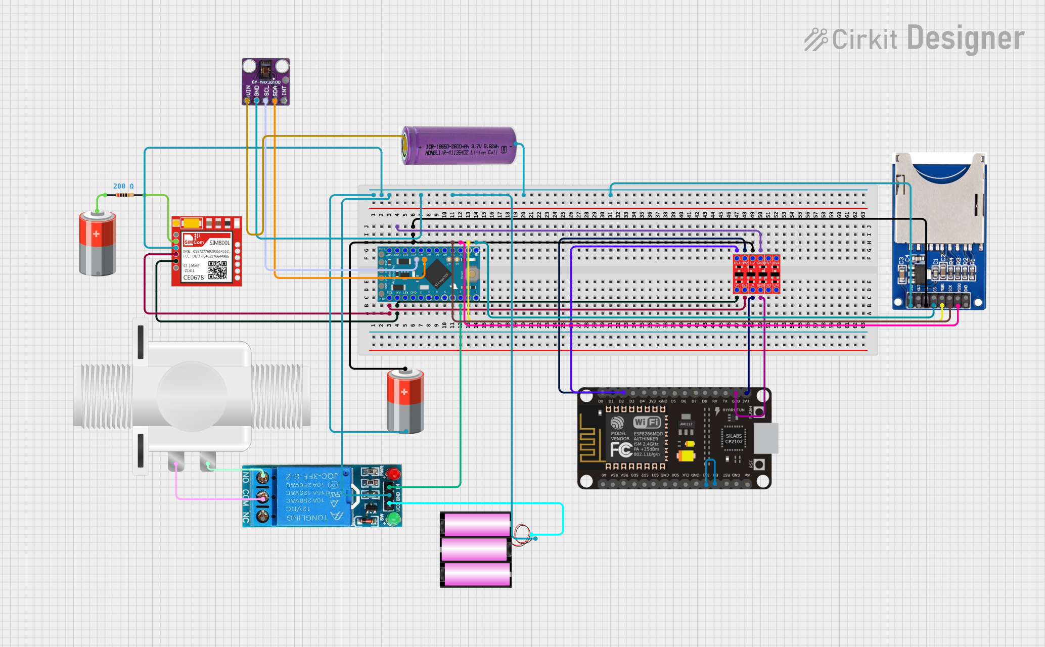
Arduino and ESP8266 Based Health Monitoring System with Remote Data Logging

Circuit Documentation
Summary
This circuit integrates a variety of components to perform a set of functions that are not explicitly defined in the provided information. The core of the circuit is an Arduino Pro Mini, which is responsible for controlling the peripherals including an ESP8266 NodeMCU, a MAX30100 pulse oximeter sensor, an SD card reader, a single-channel 12V relay, a plastic solenoid valve, a bi-directional logic level converter, a SIM800L GSM module, and various power sources. The Arduino Pro Mini also interfaces with the SD card reader for data storage. The ESP8266 NodeMCU may provide Wi-Fi capabilities, and the SIM800L module adds GSM functionality for communication. The MAX30100 sensor is likely used for health monitoring purposes. The relay controls the solenoid valve, which could be part of a fluid control system. The logic level converter ensures safe voltage levels between 5V and 3.3V devices. The circuit is powered by different batteries, each supplying the required voltage levels to the respective components.
Component List
Microcontrollers
- Arduino Pro Mini: A compact microcontroller board based on the ATmega328, used for controlling the various components in the circuit.
- ESP8266 NodeMCU: A Wi-Fi enabled microcontroller module that can be used for Internet connectivity and remote control.
Sensors and Modules
- MAX30100: An integrated pulse oximetry and heart-rate sensor module used for health monitoring.
- SIM800L: A GSM module that provides GSM/GPRS functionality for communication over a mobile network.
Storage
- SD Card Reader (2 Pins): A module for reading and writing data to an SD card, likely used for data logging purposes.
Power Control
- 12V Single Channel Relay: An electromechanical switch used for controlling high power devices, such as the solenoid valve in this circuit.
- Plastic Solenoid Valve: An electrically-controlled valve used for controlling the flow of a fluid.
Power Sources
- 5V Battery: Provides power to 5V components in the circuit.
- 12V Battery: Supplies power to the 12V relay and solenoid valve.
- 3.3V Battery: Powers the 3.3V components, such as the MAX30100 sensor.
Other Components
- Bi-Directional Logic Level Converter: A device that safely steps down 5V signals to 3.3V and steps up 3.3V to 5V.
- Resistor (200 Ohms): A passive component used to limit current or divide voltages in the circuit.
Wiring Details
Arduino Pro Mini
- A4 (SDA) connected to MAX30100 (SDA)
- A5 (SCL) connected to MAX30100 (SCL)
- VCC connected to Logic Level Converter (HV), SD Card Reader (5V), and 5V Battery (+)
- GND connected to common ground net
- D10 connected to SD Card Reader (CS)
- MOSI connected to SD Card Reader (MOSI)
- SCK connected to SD Card Reader (SCK)
- MISO connected to SD Card Reader (MISO)
- D7 connected to 12V Relay (IN)
- TXO connected to Logic Level Converter (LV2) and SIM800L (RXD) through the converter
- RXI connected to Logic Level Converter (LV1) and SIM800L (TXD) through the converter
ESP8266 NodeMCU
- D1 connected to Logic Level Converter (HV2)
- D2 connected to Logic Level Converter (HV1)
- GND connected to common ground net
- 3V3 connected to Logic Level Converter (LV) and ESP8266 NodeMCU (EN)
- EN connected to 3.3V Battery (+)
MAX30100
- Vin connected to 3.3V Battery (+)
- gnd connected to common ground net
- scl connected to Arduino Pro Mini (A5)
- sda connected to Arduino Pro Mini (A4)
SD Card Reader
- GND connected to common ground net
- 3.3V not connected
- 5V connected to Arduino Pro Mini (VCC)
- CS connected to Arduino Pro Mini (D10)
- MOSI connected to Arduino Pro Mini (MOSI)
- SCK connected to Arduino Pro Mini (SCK)
- MISO connected to Arduino Pro Mini (MISO)
12V Single Channel Relay
- GND connected to common ground net
- VCC connected to 12V Battery (+)
- IN connected to Arduino Pro Mini (D7)
- COM connected to Plastic Solenoid Valve (pin1)
- NO connected to Plastic Solenoid Valve (pin2)
Plastic Solenoid Valve
- pin1 connected to 12V Relay (COM)
- pin2 connected to 12V Relay (NO)
Bi-Directional Logic Level Converter
- HV1 connected to ESP8266 NodeMCU (D2)
- HV2 connected to ESP8266 NodeMCU (D1)
- GND connected to common ground net
- LV connected to ESP8266 NodeMCU (3V3)
- LV1 connected to Arduino Pro Mini (RXI) through SIM800L (TXD)
- LV2 connected to Arduino Pro Mini (TXO) through SIM800L (RXD)
SIM800L
- VCC connected to 5V Battery (+) through a 200 Ohm Resistor
- RXD connected to Arduino Pro Mini (TXO) through Logic Level Converter (LV2)
- TXD connected to Arduino Pro Mini (RXI) through Logic Level Converter (LV1)
- GND connected to common ground net
Resistor (200 Ohms)
- pin1 connected to 5V Battery (+)
- pin2 connected to SIM800L (VCC)
Documented Code
Arduino Pro Mini Code (sketch.ino)
void setup() {
  // put your setup code here, to run once:

}

void loop() {
  // put your main code here, to run repeatedly:

}
Note: The provided code for the Arduino Pro Mini is a template with empty setup and loop functions. Actual functionality needs to be implemented based on the specific requirements of the circuit.