Arduino Nano Controlled Ultrasonic Distance Measurement with RGB LED Feedback
Circuit Documentation
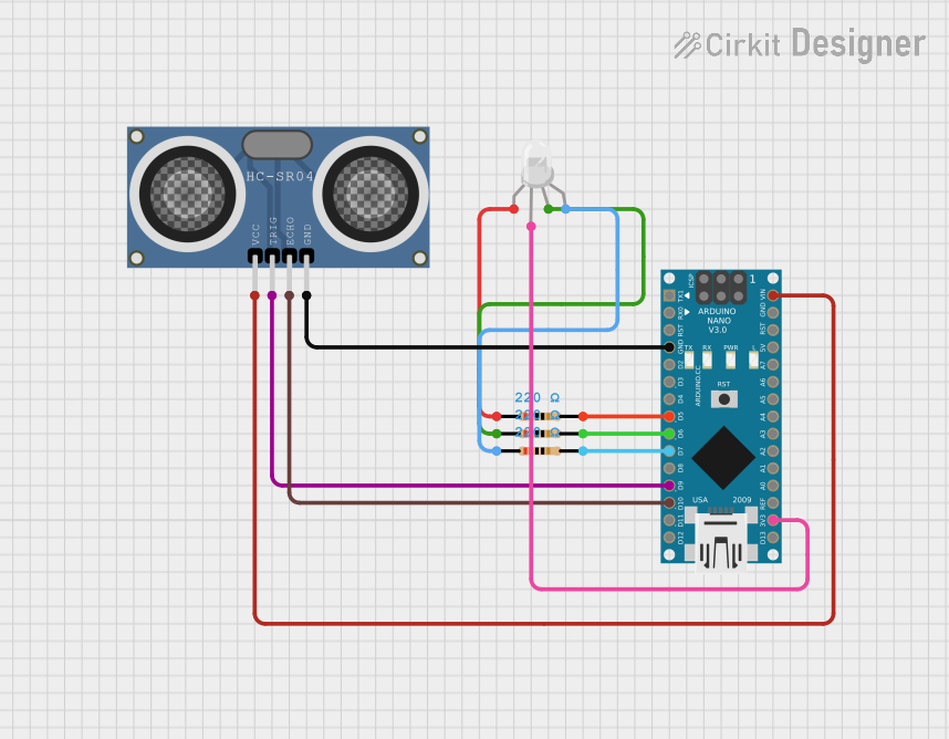
Summary of the Circuit
This circuit integrates an Arduino Nano microcontroller with an HC-SR04 Ultrasonic Distance Sensor and an RGB LED. The purpose of the circuit is to measure distances using the ultrasonic sensor and visually indicate the distance range through the color of the RGB LED. The RGB LED changes color based on the distance measured: red for close distances, green for intermediate distances, and blue for farther away. The Arduino Nano controls the sensor and the LED, and it also sends distance information to a connected computer via serial communication.
Component List
Arduino Nano
- Microcontroller board based on the ATmega328P
- It has a variety of digital and analog I/O pins
- Used as the main controller for interfacing with the ultrasonic sensor and driving the RGB LED
RGB LED (Wokwi compatible)
- A four-pin LED with red, green, and blue emitters
- Common anode configuration
- Used to display different colors based on the distance measured by the sensor
Resistor (220 Ohms)
- Three resistors with a resistance of 220 Ohms each
- Used to limit the current through the RGB LED pins
HC-SR04 Ultrasonic Distance Sensor (Wokwi Compatible)
- A module that measures distance by emitting ultrasonic waves and measuring the time taken for the echo to return
- Has VCC, TRIG, ECHO, and GND pins
- Used to measure the distance to an object in front of the sensor
Wiring Details
Arduino Nano
- GND connected to the GND pin of the HC-SR04 Ultrasonic Distance Sensor
- D5 connected to a 220 Ohm resistor (which connects to the red pin of the RGB LED)
- D6 connected to a 220 Ohm resistor (which connects to the green pin of the RGB LED)
- D7 connected to a 220 Ohm resistor (which connects to the blue pin of the RGB LED)
- D9 connected to the TRIG pin of the HC-SR04 Ultrasonic Distance Sensor
- D10 connected to the ECHO pin of the HC-SR04 Ultrasonic Distance Sensor
- VIN connected to the VCC pin of the HC-SR04 Ultrasonic Distance Sensor
- 3V3 connected to the common anode (COM) of the RGB LED
RGB LED (Wokwi compatible)
- COM connected to the 3V3 pin of the Arduino Nano
- R connected to a 220 Ohm resistor (which connects to D5 of the Arduino Nano)
- G connected to a 220 Ohm resistor (which connects to D6 of the Arduino Nano)
- B connected to a 220 Ohm resistor (which connects to D7 of the Arduino Nano)
Resistor (220 Ohms)
- Three resistors each with one end connected to the D5, D6, and D7 pins of the Arduino Nano, and the other end connected to the R, G, and B pins of the RGB LED respectively
HC-SR04 Ultrasonic Distance Sensor (Wokwi Compatible)
- VCC connected to the VIN pin of the Arduino Nano
- TRIG connected to the D9 pin of the Arduino Nano
- ECHO connected to the D10 pin of the Arduino Nano
- GND connected to the GND pin of the Arduino Nano
Documented Code
/*
 * Arduino Nano with HC-SR04 Ultrasonic Sensor and RGB LED
 * This code initializes the sensor and reads the distance
 * measured by the sensor, then changes the color of the RGB LED
 * based on the distance. The RGB LED is connected to pins D5, D6, and D7.
 */

const int trigPin = 9; // TRIG pin connected to D9
const int echoPin = 10; // ECHO pin connected to D10
const int redPin = 5; // Red LED pin connected to D5
const int greenPin = 6; // Green LED pin connected to D6
const int bluePin = 7; // Blue LED pin connected to D7

void setup() {
  // Initialize serial communication
  Serial.begin(9600);
  // Set the TRIG pin as an OUTPUT
  pinMode(trigPin, OUTPUT);
  // Set the ECHO pin as an INPUT
  pinMode(echoPin, INPUT);
  // Set the RGB LED pins as OUTPUT
  pinMode(redPin, OUTPUT);
  pinMode(greenPin, OUTPUT);
  pinMode(bluePin, OUTPUT);
}

void loop() {
  // Clear the TRIG pin
  digitalWrite(trigPin, LOW);
  delayMicroseconds(2);
  // Set the TRIG pin HIGH for 10 microseconds
  digitalWrite(trigPin, HIGH);
  delayMicroseconds(10);
  digitalWrite(trigPin, LOW);
  // Read the ECHO pin
  long duration = pulseIn(echoPin, HIGH);
  // Calculate the distance
  long distance = duration * 0.034 / 2;
  // Print the distance to the Serial Monitor
  Serial.print("Distance: ");
  Serial.print(distance);
  Serial.println(" cm");
  // Change the color of the RGB LED based on distance
  if (distance < 10) {
    setColor(255, 0, 0); // Red
  } else if (distance < 20) {
    setColor(0, 255, 0); // Green
  } else {
    setColor(0, 0, 255); // Blue
  }
  // Wait for a short period before the next measurement
  delay(500);
}

void setColor(int red, int green, int blue) {
  analogWrite(redPin, red);
  analogWrite(greenPin, green);
  analogWrite(bluePin, blue);
}
This code is designed to be uploaded to an Arduino Nano. It initializes the pins connected to the HC-SR04 Ultrasonic Distance Sensor and the RGB LED, performs distance measurements, and sets the color of the RGB LED based on the measured distance. Serial communication is used to output the distance values to a connected computer for monitoring.