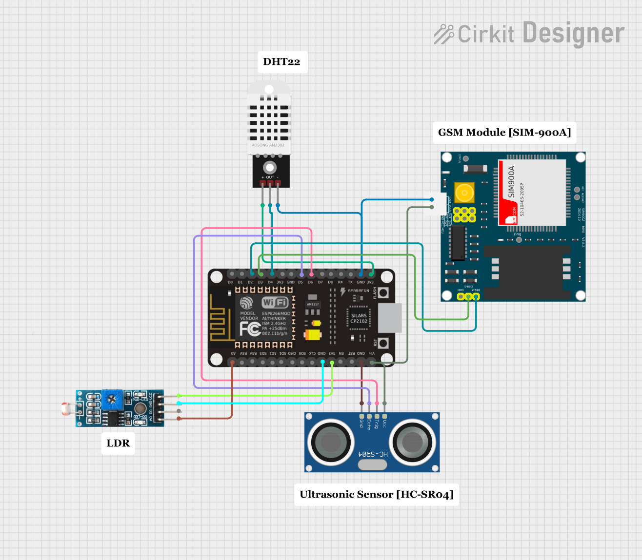
ESP8266 NodeMCU-Based Environmental Monitoring System with SIM900A GSM Communication

Circuit Documentation
Summary
The circuit in question is designed to interface various sensors and modules with an ESP8266 NodeMCU microcontroller. The components include a light-dependent resistor (LDR) module, a DHT22 temperature and humidity sensor, an HC-SR04 ultrasonic distance sensor, and a SIM900A GSM module. The ESP8266 NodeMCU serves as the central processing unit, reading sensor data and communicating with the GSM module. The circuit is powered through the NodeMCU's VIN pin, which is connected to the 5V outputs of the SIM900A and the HC-SR04. Ground connections are shared among all components.
Component List
Module LDR
- Pins: VCC, GND, DO, AO
- Description: A light-dependent resistor module used to measure light intensity.
DHT22
- Pins: +, Out, -
- Description: A sensor for measuring temperature and humidity.
ESP8266 NodeMCU
- Pins: D0, D1, D2, D3, D4, 3V3, GND, D5, D6, D7, D8, RX, TX, A0, RSV, SD3, SD2, SD1, CMD, SD0, CLK, EN, RST, VIN
- Description: A microcontroller with Wi-Fi capabilities, used as the main controller for the circuit.
HC-SR04 Ultrasonic Sensor
- Pins: VCC, TRIG, ECHO, GND
- Description: A sensor used to measure distance via ultrasonic waves.
SIM900A
- Pins: GND, DB9-3 (RXD), DB9-2 (TXD), 5V, 3VR, 5VR, 3VT, 5VT, VCC, Ring, RESTART, RESET, STATUS
- Description: A GSM module for cellular communication.
Wiring Details
Module LDR
- VCC connected to NodeMCU 3V3
- GND connected to NodeMCU GND
- AO connected to NodeMCU A0
DHT22
- + connected to NodeMCU 3V3
- Out connected to NodeMCU D4
- - connected to NodeMCU GND
ESP8266 NodeMCU
- 3V3 connected to LDR VCC and DHT22 +
- GND connected to LDR GND, DHT22 -, HC-SR04 GND, and SIM900A GND
- D2 connected to SIM900A TXD
- D3 connected to SIM900A RXD
- D4 connected to DHT22 Out
- D5 connected to HC-SR04 ECHO
- D6 connected to HC-SR04 TRIG
- A0 connected to LDR AO
- VIN connected to SIM900A 5V and HC-SR04 VCC
HC-SR04 Ultrasonic Sensor
- VCC connected to NodeMCU VIN
- TRIG connected to NodeMCU D6
- ECHO connected to NodeMCU D5
- GND connected to NodeMCU GND
SIM900A
- DB9-2 (TXD) connected to NodeMCU D2
- DB9-3 (RXD) connected to NodeMCU D3
- GND connected to NodeMCU GND
- 5V connected to NodeMCU VIN
Documented Code
ESP8266 NodeMCU Code (sketch.ino)
void setup() {
  // put your setup code here, to run once:

}

void loop() {
  // put your main code here, to run repeatedly:

}
DHT22 Code (sketch.ino)
void setup() {
  // put your setup code here, to run once:

}

void loop() {
  // put your main code here, to run repeatedly:

}
Note: The provided code for both the ESP8266 NodeMCU and the DHT22 is a template with empty setup and loop functions. The actual implementation should include initialization of the sensors and communication interfaces, as well as the logic for reading sensor data and sending/receiving data via the GSM module.