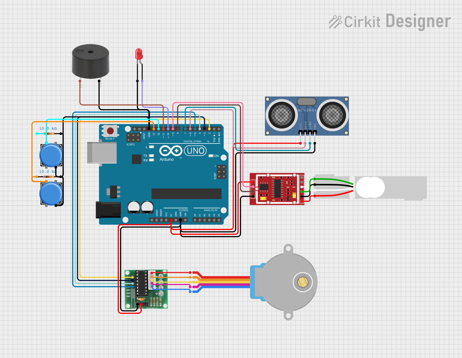
Arduino UNO-Based Measurement and Alert System with Stepper Motor Control

Circuit Documentation
Summary
This circuit integrates various components controlled by an Arduino UNO microcontroller to perform a range of functions. It includes a stepper motor driven by a ULN 2003 driver, a buzzer, an LED, two pushbuttons, a load cell interfaced with an HX711 weighing sensor module, and an HC-SR04 ultrasonic distance sensor. The circuit is designed to interact with the physical environment using the stepper motor, provide audio-visual feedback through the buzzer and LED, and measure distance and weight with the sensors.
Component List
- Arduino UNO: A microcontroller board based on the ATmega328P, with digital and analog I/O pins.
- Adafruit Gear-Reduced Stepper Motor (small): A small stepper motor for precise motion control.
- ULN 2003: A 7-channel Darlington transistor array for driving high-current loads.
- Buzzer: An audio signaling device.
- LED (Red, Two Pin): A red light-emitting diode for visual indication.
- Pushbutton (x2): Momentary push-to-make switches for user input.
- Load Cell (Red/white/black/green): A transducer that converts force into an electrical signal.
- HC-SR04 Ultrasonic Distance Sensor: A sensor for measuring distance via ultrasonic waves.
- HX711 Weighing Sensor Module: An ADC converter for load cells, used for weight measurement.
- Resistor (x2): 10kΩ resistors used for pull-up or pull-down configurations.
Wiring Details
Arduino UNO
- 5V and GND pins provide power to the ULN 2003, HC-SR04, and HX711 modules.
- Digital pins D2 to D13 are used for interfacing with the ULN 2003, buzzer, LED, HX711, and HC-SR04.
Adafruit Gear-Reduced Stepper Motor (small)
- Connected to the ULN 2003 driver to receive control signals for movement.
ULN 2003
- IN1 to IN4 pins are connected to Arduino digital pins D2 to D5 for stepper motor control.
- COIL1 to COIL5 pins are connected to the corresponding stepper motor coil pins.
Buzzer
- Connected to Arduino digital pin D11 and GND.
LED (Red, Two Pin)
- Anode connected to Arduino digital pin D10.
- Cathode connected to GND through a pushbutton and resistor network.
Pushbuttons
- One side of each pushbutton is connected to GND through a 10kΩ resistor.
- The other side of each pushbutton is connected to Arduino digital pins D12 and D13.
Load Cell (Red/white/black/green)
- Connected to the HX711 module for weight measurement.
HC-SR04 Ultrasonic Distance Sensor
- VCC and GND pins are connected to 5V and GND for power.
- TRIG and ECHO pins are connected to Arduino digital pins D6 and D7 for distance measurement.
HX711 Weighing Sensor Module
- E+, A-, E-, and A+ pins are connected to the corresponding pins on the load cell.
- VCC and GND pins are connected to 5V and GND for power.
- CK/TX and DO/RX pins are connected to Arduino digital pins D9 and D8 for data communication.
Resistor (10kΩ)
- Connected between GND and the pushbuttons to provide a stable low signal when the buttons are not pressed.
Documented Code
void setup() {
  // put your setup code here, to run once:

}

void loop() {
  // put your main code here, to run repeatedly:

}
The provided code is a template with empty setup() and loop() functions, which are the entry points for Arduino sketches. The setup() function is called once when the sketch starts and is used to initialize settings, while the loop() function runs repeatedly, allowing the microcontroller to perform operations based on the circuit's design. The actual implementation details would be added to these functions based on the desired behavior of the circuit.