Cirkit Designer
Your all-in-one circuit design IDE
Home /
Project Documentation
Arduino UNO Based Weight Threshold Alert System with HX711 and LED Indicator
Circuit Documentation
Summary of the Circuit
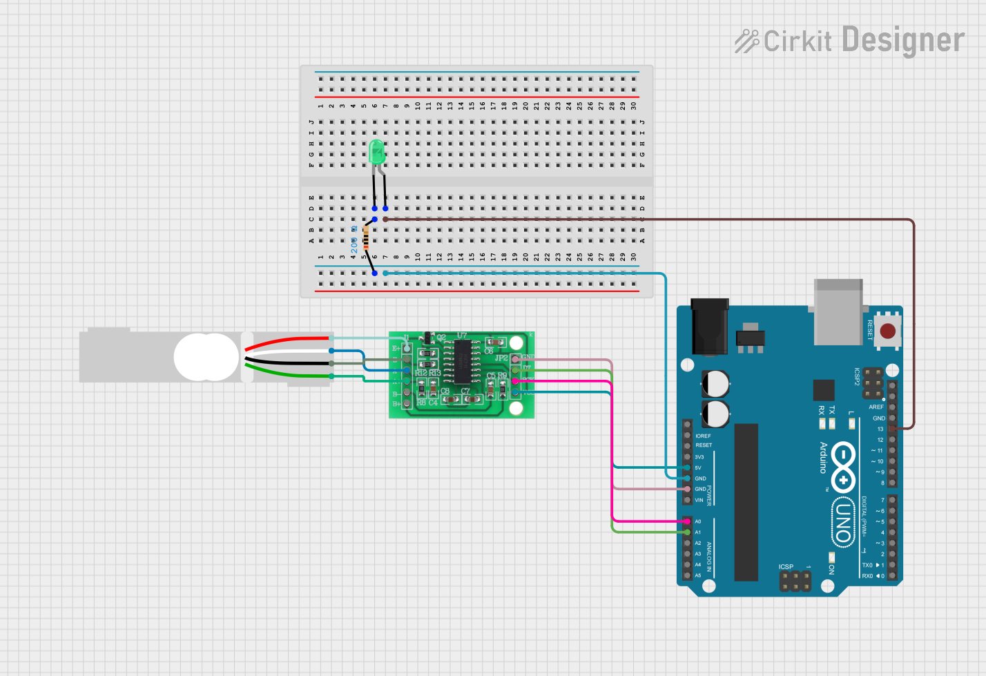
This circuit is designed to measure weight using a load cell and display the readings on the Arduino UNO's serial monitor. It includes an HX711 amplifier to interface the load cell with the Arduino. An LED is used as an indicator that lights up when the measured weight exceeds a predefined threshold. The Arduino UNO microcontroller is programmed to read the weight data from the HX711 and control the LED accordingly.
Component List
Arduino UNO
- Microcontroller board based on the ATmega328P
- It has 14 digital input/output pins, 6 analog inputs, a 16 MHz quartz crystal, a USB connection, a power jack, an ICSP header, and a reset button.
Load Cell - Red/white/black/green
- A transducer that converts force into an electrical signal.
- It has four wires corresponding to Excitation+ (E+), Excitation- (E-), Amplifier+ (A+), and Amplifier- (A-).
Resistor
- A passive two-terminal electrical component that implements electrical resistance as a circuit element.
- Resistance: 200 Ohms
LED: Two Pin (green)
- A light-emitting diode that emits green light.
- It has two terminals: an anode and a cathode.
HX711 - Bridge Sensor Interface
- A precision 24-bit analog-to-digital converter (ADC) designed for weigh scales and industrial control applications to interface directly with a bridge sensor.
Wiring Details
Arduino UNO
- 5V: Supplies power to the HX711.
- GND: Connected to the ground of the circuit.
- A0: Connected to the SCK - CLOCK (IN) pin of the HX711.
- A1: Connected to the DATA (OUT) pin of the HX711.
- D13: Connected to the anode of the LED through a 200 Ohm resistor.
Load Cell - Red/white/black/green
- E+: Connected to the E+ of the HX711.
- A-: Connected to the A- of the HX711.
- E-: Connected to the E- of the HX711.
- A+: Connected to the A+ of the HX711.
Resistor
- Pin1: Connected to the GND of the circuit.
- Pin2: Connected to the cathode of the LED.
LED: Two Pin (green)
- Anode: Connected to D13 on the Arduino UNO through a 200 Ohm resistor.
- Cathode: Connected to the GND of the circuit through a resistor.
HX711 - Bridge Sensor Interface
- 3.3/3.5V Supply: Powered by the 5V pin of the Arduino UNO.
- GND - GROUND: Connected to the GND of the Arduino UNO.
- SCK - CLOCK (IN): Connected to A0 on the Arduino UNO.
- DATA (OUT): Connected to A1 on the Arduino UNO.
- E+/E-/A+/A-: Interfaced with the corresponding pins of the Load Cell.
Documented Code
#include "HX711.h"

// Pin setup for HX711 amplifier
#define DOUT  A1
#define CLK   A0

// Threshold in kg
float thresholdWeight = 5.0;

HX711 scale;

int ledPin = 13;

void setup() {
  Serial.begin(9600);

  // Initialize HX711
  scale.begin(DOUT, CLK);

  // Calibrate the scale (this value may vary, you can calibrate it manually)
  scale.set_scale(2280.f);  // Adjust to match your load cell calibration factor
  scale.tare();  // Reset scale to 0

  // Setup LED pin
  pinMode(ledPin, OUTPUT);
}

void loop() {
  // Get weight in kg
  float weight = scale.get_units(10);  // Average of 10 readings

  // Display weight on serial monitor
  Serial.print("Weight: ");
  Serial.print(weight);
  Serial.println(" kg");

  // Check if the weight exceeds threshold
  if (weight >= thresholdWeight) {
    // Blink LED if the weight exceeds 5kg
    digitalWrite(ledPin, HIGH);
    delay(500);
    digitalWrite(ledPin, LOW);
    delay(500);
  } else {
    // Keep LED off if below threshold
    digitalWrite(ledPin, LOW);
  }

  delay(1000);  // Delay for 1 second before next reading
}
This code is designed to run on the Arduino UNO. It initializes the HX711 amplifier and the load cell, performs tare to zero the scale, and continuously reads the weight. If the weight exceeds the threshold of 5 kg, it blinks the LED connected to pin D13. The weight is also printed to the serial monitor for observation.