
ESP32-Based Health Monitoring System with MAX30102 and DHT11 Sensors, Wi-Fi Enabled
View and Edit Project In Cirkit Designer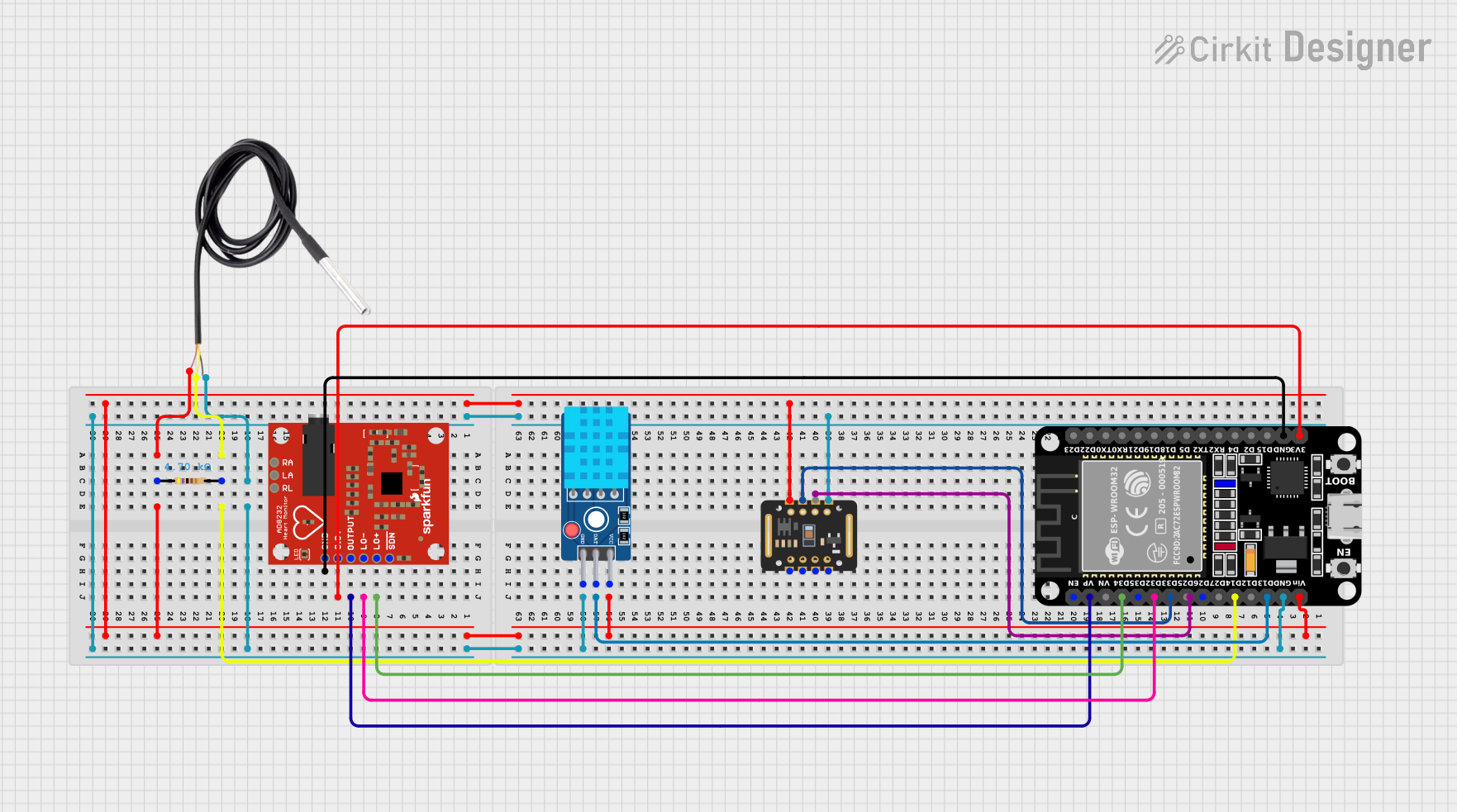
Health Monitoring System Documentation
Summary
This document provides a detailed overview of a health monitoring system built using an ESP32 microcontroller. The system integrates various sensors, including a MAX30102 pulse oximeter, a DHT11 temperature and humidity sensor, a DS18B20 temperature sensor, and an AD8232 heart rate monitor. The ESP32 collects data from these sensors and sends it to a Blynk application for real-time monitoring.
Component List
ESP32 (30 pin)
- Description: A powerful microcontroller with built-in Wi-Fi and Bluetooth capabilities.
- Pins: EN, VP, VN, D34, D35, D32, D33, D25, D26, D27, D14, D12, D13, GND, Vin, D23, D22, TX0, RX0, D21, D19, D18, D5, TX2, RX2, D4, D2, D15, 3V3
MAX30102
- Description: A pulse oximeter and heart-rate sensor module.
- Pins: VIN, SDA, SCL, GND, RD, IRD, INT
DHT11 Sensor V2
- Description: A temperature and humidity sensor.
- Pins: GND, DAT, VCC
Resistor
- Description: A 4700 Ohms resistor.
- Pins: pin1, pin2
- Properties: Resistance: 4700 Ohms
DS18B20
- Description: A digital temperature sensor.
- Pins: signal, GND, vcc
AD8232 HeartRate Monitor
- Description: A heart rate monitor module.
- Pins: GND, 3.3v, OUTPUT, LO-, LO+, SDN, RA, LA, RL
Wiring Details
ESP32 (30 pin)
- D13 connected to DAT of DHT11 Sensor V2
- Vin connected to VCC of DHT11 Sensor V2, pin1 of Resistor, vcc of DS18B20, VIN of MAX30102
- GND connected to GND of DHT11 Sensor V2, GND of DS18B20, GND of MAX30102, GND of AD8232 HeartRate Monitor
- D34 connected to LO+ of AD8232 HeartRate Monitor
- D32 connected to LO- of AD8232 HeartRate Monitor
- VP connected to OUTPUT of AD8232 HeartRate Monitor
- 3V3 connected to 3.3v of AD8232 HeartRate Monitor
- D14 connected to signal of DS18B20 and pin2 of Resistor
- D33 connected to SDA of MAX30102
MAX30102
- VIN connected to Vin of ESP32 (30 pin)
- SDA connected to D33 of ESP32 (30 pin)
- GND connected to GND of ESP32 (30 pin)
DHT11 Sensor V2
- DAT connected to D13 of ESP32 (30 pin)
- VCC connected to Vin of ESP32 (30 pin)
- GND connected to GND of ESP32 (30 pin)
Resistor
- pin1 connected to Vin of ESP32 (30 pin)
- pin2 connected to signal of DS18B20 and D14 of ESP32 (30 pin)
DS18B20
- signal connected to pin2 of Resistor and D14 of ESP32 (30 pin)
- GND connected to GND of ESP32 (30 pin)
- vcc connected to Vin of ESP32 (30 pin)
AD8232 HeartRate Monitor
- LO+ connected to D34 of ESP32 (30 pin)
- LO- connected to D32 of ESP32 (30 pin)
- OUTPUT connected to VP of ESP32 (30 pin)
- 3.3v connected to 3V3 of ESP32 (30 pin)
- GND connected to GND of ESP32 (30 pin)
Documented Code
#define BLYNK_TEMPLATE_ID "TMPL3HGdsjELo"
#define BLYNK_TEMPLATE_NAME "Health Monitoring System"
#define BLYNK_AUTH_TOKEN "xiEfxFkWFg8D8jkJAsNh1QoqXrYfTCC3"

#include <Wire.h>
#include <WiFi.h>
#include <BlynkSimpleEsp32.h>
#include "MAX30105.h"
#include "spo2_algorithm.h"
#include "heartRate.h"
#include <OneWire.h>
#include <DallasTemperature.h>
#include <DHT.h>

// Wi-Fi Credentials
char auth[] = "xiEfxFkWFg8D8jkJAsNh1QoqXrYfTCC3"; // Your Blynk Auth Token
char ssid[] = "OnePlus 10T 5G"; // Your WiFi credentials
char pass[] = "35743574"; // Your WiFi password

BlynkTimer timer; // Blynk timer

// MAX30105 Settings
MAX30105 particleSensor;
#define MAX_BRIGHTNESS 255
#define REPORTING_PERIOD_MS 1000 // Frequency of updates sent to Blynk app in ms

// GPIO pins for MAX30105
byte pulseLED = 2; // Onboard LED on ESP32
byte readLED = 19; // Blinks with each data read

// DS18B20 Settings
#define DS18B20_PIN 14  // DS18B20 data pin connected to GPIO14
OneWire oneWire(DS18B20_PIN);
DallasTemperature ds18b20(&oneWire);

// DHT11 Settings
#define DHTPIN 13  // DHT11 data pin connected to GPIO13
#define DHTTYPE DHT11
DHT dht(DHTPIN, DHTTYPE);

// Variables for MAX30105
uint32_t tsLastReport = 0; // Timestamp for last report
int32_t bufferLength; // Data length
int32_t spo2; // SpO2 value
int8_t validSPO2; // Indicator for valid SpO2 calculation
int32_t heartRate; // Heart rate value
int8_t validHeartRate; // Indicator for valid heart rate calculation

// Buffer arrays for readings
#define MAX_BUFFER_SIZE 100
uint32_t redBuffer[MAX_BUFFER_SIZE]; // Buffer for red LED values
uint32_t irBuffer[MAX_BUFFER_SIZE]; // Buffer for IR LED values

// Simple Moving Average (SMA) variables
#define SMA_WINDOW_SIZE 5 // Number of samples to average
int heartRateHistory[SMA_WINDOW_SIZE] = {0};
int spo2History[SMA_WINDOW_SIZE] = {0};
int heartRateIndex = 0;

// Define a threshold for the IR value to check finger presence
const uint32_t threshold = 10000; // Adjust this value based on testing

int calculateSMA(int newValue, int *history) {
    int sum = 0;
    history[heartRateIndex] = newValue;
    heartRateIndex = (heartRateIndex + 1) % SMA_WINDOW_SIZE;

    for (int i = 0; i < SMA_WINDOW_SIZE; i++) {
        sum += history[i];
    }
    return sum / SMA_WINDOW_SIZE;
}

// Send sensor data function
void sendSensorData() {
    // Request temperature from DS18B20
    ds18b20.requestTemperatures();

    // Read from DS18B20 (Body Temperature)
    float tempF = ds18b20.getTempFByIndex(0);
    if (tempF == -196.60) {
        Serial.println("Failed to read from DS18B20 sensor!");
    } else {
        Serial.print("Body Temperature: ");
        Serial.print(tempF);
        Serial.println("°F");
        Blynk.virtualWrite(V2, tempF); // Send Body Temperature to Blynk Virtual Pin V2
    }

    // Read from DHT11
    float h = dht.readHumidity();
    float t = dht.readTemperature();  // DHT11 gives temperature in Celsius
    if (isnan(h) || isnan(t)) {
        Serial.println("Failed to read from DHT11 sensor!");
    } else {
        Serial.print("Humidity: ");
        Serial.print(h);
        Serial.print("%  ");
        Serial.print("Room Temperature: ");
        Serial.print(t);
        Serial.println("°C");
        Blynk.virtualWrite(V1, h); // Send Humidity to Blynk Virtual Pin V1
        Blynk.virtualWrite