
ESP32-Based Portable Smart Speaker with Audio Input Processing
View and Edit Project In Cirkit Designer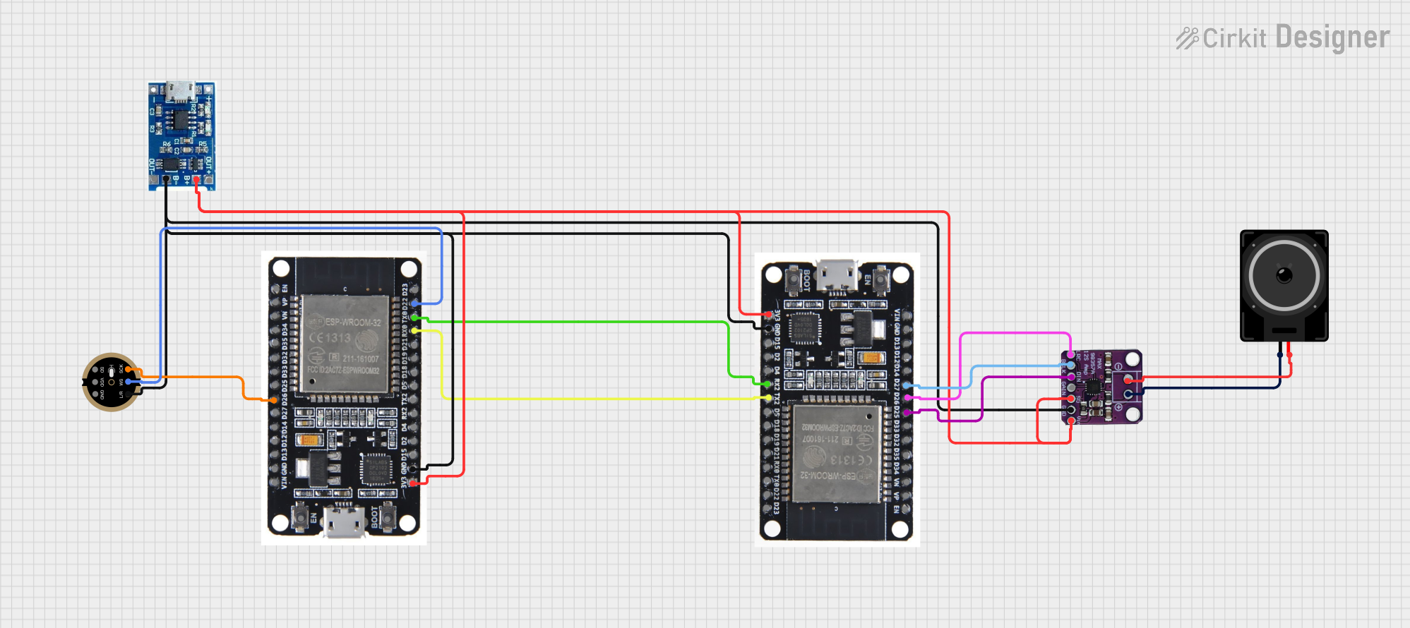
Circuit Documentation
Summary of the Circuit
This circuit appears to be designed for audio processing and output, featuring two ESP32 microcontrollers, an INMP441 microphone, a Max98357 audio amplifier, and a loudspeaker. The circuit also includes a lipo battery charger module for power management. The ESP32s are responsible for handling digital signals and possibly for wireless communication, given their capabilities. The INMP441 is an I2S digital microphone for capturing audio, and the Max98357 is an I2S class D amplifier that drives the loudspeaker. The lipo battery charger module ensures that a connected lithium polymer battery is charged and provides power to the circuit.
Component List
ESP32
- Description: A microcontroller with Wi-Fi and Bluetooth capabilities, equipped with multiple GPIOs for interfacing with various peripherals.
- Purpose: To process digital signals, control the audio data flow, and possibly handle wireless communication.
INMP441 Front Mic
- Description: An I2S digital output microphone, capable of converting acoustic signals into digital signals.
- Purpose: To capture audio signals for processing by the ESP32.
Loudspeaker
- Description: An electroacoustic transducer that converts an electrical audio signal into a corresponding sound.
- Purpose: To output audio signals after amplification.
Max98357
- Description: An I2S class D audio amplifier with a digital input.
- Purpose: To amplify the digital audio signal and drive the loudspeaker.
Lipo Battery Charger Module
- Description: A charging circuit for lithium polymer batteries, with output terminals for powering the circuit.
- Purpose: To charge the battery and provide power to the circuit components.
Wiring Details
ESP32
3V3connected to Max98357VINand lipo battery charger moduleB+GNDconnected to Max98357GND, INMP441GND, and lipo battery charger moduleB-D26connected to INMP441SCKD22connected to INMP441WSRX0connected to the second ESP32'sTX2TX0connected to the second ESP32'sRX2D25connected to Max98357DIN(second ESP32)D26connected to Max98357LRC(second ESP32)D27connected to Max98357BLCK(second ESP32)
INMP441 Front Mic
SCKconnected to ESP32D26WSconnected to ESP32D22GNDconnected to ESP32GNDL/Rnot connected (left/right channel selection, typically tied to GND or VDD)
Loudspeaker
pin1connected to Max98357+pin2connected to Max98357-
Max98357
SDnot connected (shutdown pin, typically tied to VDD or GND)GAINnot connected (gain selection pin, typically tied to VDD or GND)VINconnected to ESP323V3GNDconnected to ESP32GNDDINconnected to ESP32D25(second ESP32)LRCconnected to ESP32D26(second ESP32)BLCKconnected to ESP32D27(second ESP32)+connected to Loudspeakerpin1-connected to Loudspeakerpin2
Lipo Battery Charger Module
B+connected to ESP323V3B-connected to ESP32GNDOUT+andOUT-not connected (output terminals for the battery)
Documented Code
No code has been provided for the microcontrollers in the circuit. Typically, the code would initialize the hardware peripherals (such as I2S interfaces for the microphone and amplifier), handle the audio data processing, and manage any communication protocols if the ESP32s are used for wireless connectivity. The code would also include power management routines for safe battery charging and monitoring.